Posted on 5 Comments

Precision wobble?

Today’s post is all about freedom. And the Queen.

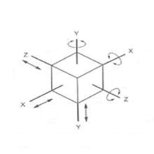
It seems to me that the design of mechanical systems might be described most simply as the selection of a set of idealized rules that, taken together, define how objects are allowed to move with respect to themselves and one another. For example: in addition to turning, the front tires on your car can rotate to the left and right (the steering) and move up and down (the suspension), but bad things have happened or will likely happen if they move either along or perpendicular to the direction of travel of the car. These rules or constraints are most often defined in three-dimensional Euclidean space in which there are three imaginary axes, each representing a single dimension, that pass through the centre of an object and (with engineering’s typical disregard for unintended double entendre) 12 degrees of freedom, or ways in which that object might move with respect to the axes: it can be translated, moved like a chess piece, in six directions, left-right, front-back and (unlike normal chess pieces) up-down and rotated backwards or forwards around the same three axes.

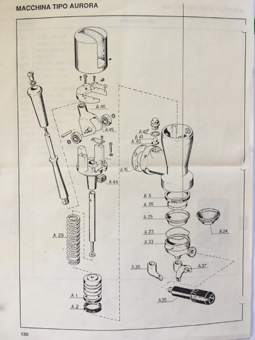
So before I get to the first production run of the pieces of the Lapera lever group, I thought it was worth revisiting the prototype piston assembly that I made some time ago. Rather than the fixed piston head and piston rod design typically used on most contemporary lever groups, I opted for a slightly more complicated articulated or floating-head design. The downside of complexity of course is that it always comes at a cost: more parts to make, more parts to assemble. The upside, which I think considerably offsets the disadvantages, is that the articulated piston is self-aligning: it automatically compensates for angular misalignment and eccentricity between the axes of the cylinder bore and the piston rod. This results in loads and consequent wear patterns on the piston seals that are more symmetrical. Even wear on the seals promotes seal longevity – which is a good thing!

The piston mechanism is perhaps best explained by an analogy to a part of the human anatomy: the wrist. Your hand is free to wave from side to side (like the Queen),

forwards and backwards (like Mikey)

and also to rotate (although this is not actually a design requirement for the piston assembly but I couldn’t resist the plastic, solar-powered Queen).

These rotations, or degrees of freedom, have limits of course; otherwise it gets really weird and creepy (think The Exorcist). In addition to rotating, the wrist permits the piston to translate laterally – similar (though not actually via the same mechanism) to another body part: the head.

So the piston assembly is sort of like a wrist, or a head, or maybe a neck. I don’t know anymore. I guess body part analogies only get you so far when trying to describe mechanisms. But I, at least, enjoyed the animated gifs. The upshot of all of this is that the chosen set of constraints embodied in the design of the wrist allow and restrict the 12 different types of motion and permit the force from the seals as they press against the cylinder wall to rotate and translate the piston into perfect alignment with the bore. Or perhaps you got it months ago and I could have saved myself a lot of writing by just posting another gif:

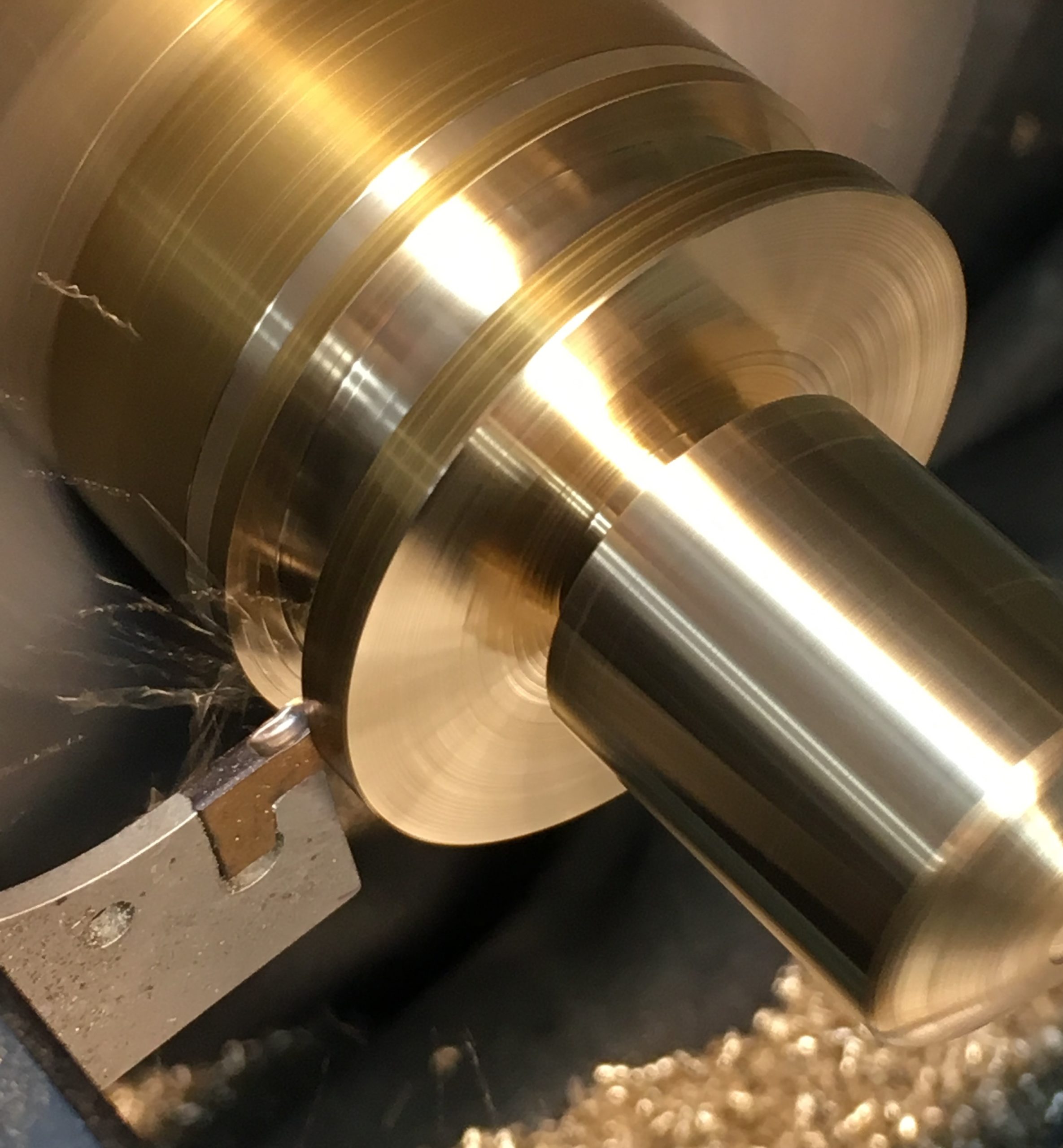
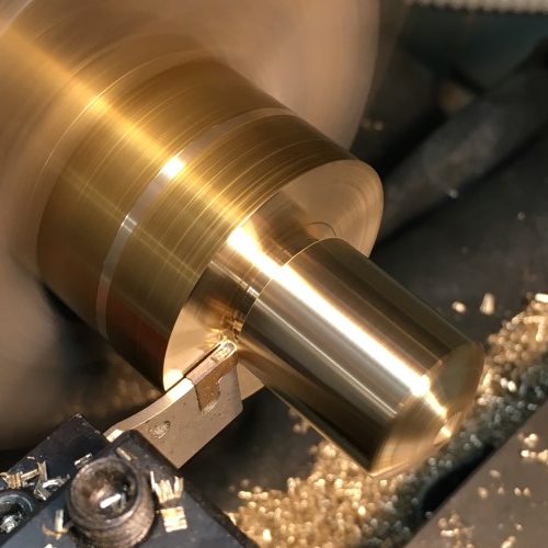
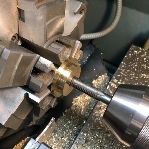
Here is a reprise of the fabrication process for the prototype of what I am still insisting on calling the wrist. Starting from a piece of 2″ C360 brass round bar stock:

Two slight angle cuts on the tip approximate a radius – this is quicker to setup than cutting an actual arc and makes little difference to functionality.

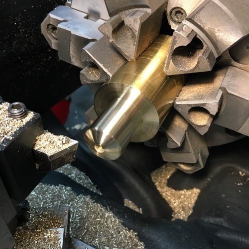
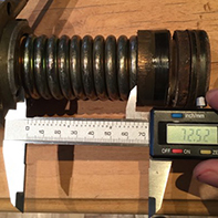
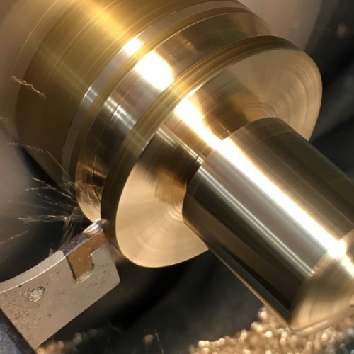
Then, using a cut-off/grooving tool, we add an undercut below what will be the flange. Spoiler: this is the clever bit of the design.

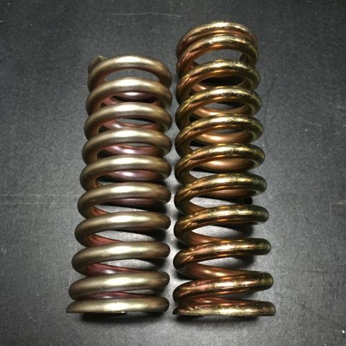
Another wider groove is cut above the flange to create the boss that will align the spring.

Then the part is cut off the stock…

…and flipped around to be drilled…

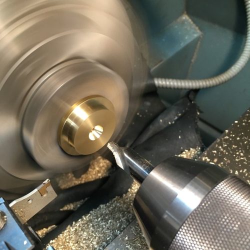
…and tapped with an M10 thread.

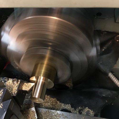
Then the part is moved over to the milling machine to complete the remaining features. This process starts with finding the centre with a touch-probe.

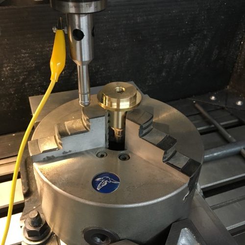
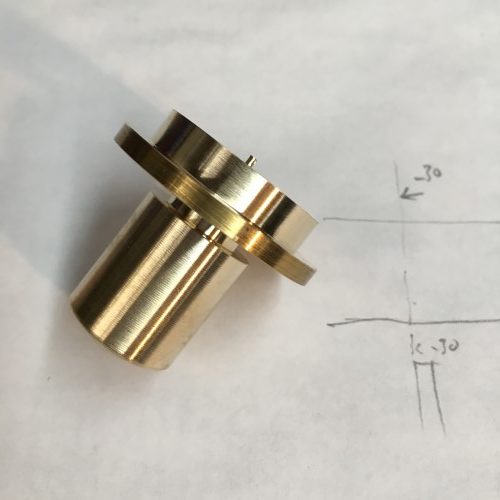
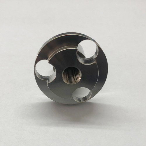
Then three clearing holes are drilled in the flange and boss.

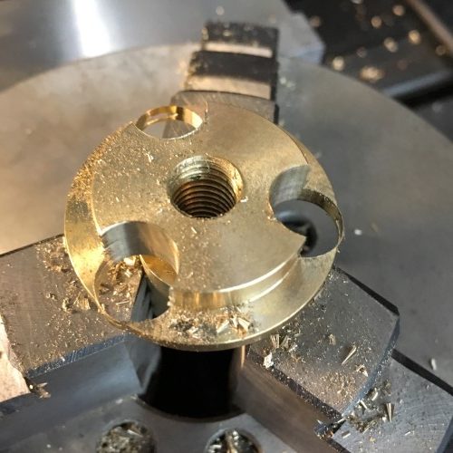
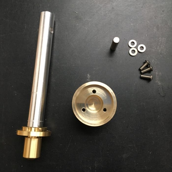
After a little cleanup – a finished wrist prototype.

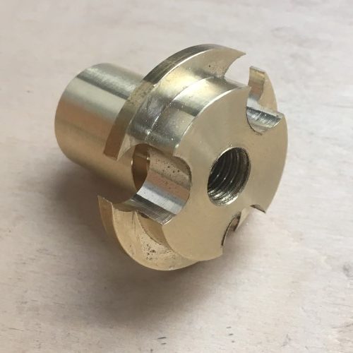
And here, with some very slight dimensional tweaks to adjust the permissible amounts of rotation and translation, is the production wrist part in the final material – AISI 304 stainless steel.
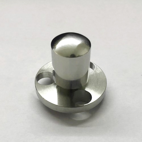
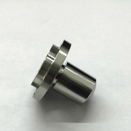
Mmmmmm – shiny :)

Next post will be on the piston. Can’t bear the suspense myself.

Posted on 1 Comment

The rite of spring

IGOR STRAVINSKY – ERICH AUERBACH / GETTY IMAGES

So Stravinsky’s ballet caused a riot… perhaps it was the shocking juxtaposition of pagan and modern Weltanschauungen, maybe the audience just didn’t like the music. What can I say? Springs are contentious. With that warning, I shall begin trying to unravel the (minor) mysteries of one particular spring.

A little more than a year ago, it was brought to my attention that replacement springs for the Brugnetti Aurora lever group were no longer available. I checked a number of suppliers and looked for substitutes without any success and I immediately went to my local parts dealer and bought the rest of their stock – a shockingly large number: four.

This is a problem if you are me and want to make new groups, or, if you are not me, repair old ones. So I took the dive into spring design and started to think a bit more carefully about a part that I had presumed was going to be “off the shelf”.

I have since come to the conclusion, for a number of reasons that will further elucidated, that the spring that was sold to me as a replacement for part number A.29 for the Aurora group, may not be, well, a replacement for part number A.29.

When I changed the spring on my first machine (well before I embarked on this voyage deep into the jungle down the Congo River) I noticed that the new one was a little taller than the original, making it quite a bit more difficult to install. Installed it was however, and I thought no more about it. That particular machine dates from 1987 and was rebuilt by a local dealer in the mid 90s – but may well have kept its original spring given how much of a hassle they are to change.

Under normal operation, springs will deliver an amount of force that is directly proportional to the distance they are compressed: F = kx (where F is Force, x displacement and k is the spring constant). Put another way the spring constant is simply how much force the spring imparts per unit of compression. So determining the spring constant can be done by measuring force versus displacement. This is the setup used – the force gauge (i.e. bathroom scale) isn’t ideal because of the built-in “intelligence” which automatically tares (zeros out) small readings and shuts off the display, but it does measure up to 175Kg. Displacement is measured using a digital height gauge (not shown) that (as so long as the same datums are used and the gauge isn’t re-zeroed) provides more accuracy than required with enough precision (I can never keep those straight).

I believe that I have identified three different springs that were installed in the Aurora group at various stages:

The replacement “after-market” spring from the local dealer which has an uncompressed length of 133mm.
Antique spring #1 – which has an uncompressed length of 128mm.
Antique spring #2 – which has an uncompressed length of 116mm.

Here are the compression versus force profiles of those three plus a fourth new prototype spring.

The two trials of the after-market 133mm spring suffer from some measurement error – i.e. if you extend the lines back towards the X axis, they don’t intersect the origin coordinates; which they should, as zero spring displacement results in zero force. If they were to be normalized (i.e. shifted down until they would intersect the origin if extended) you can see that they correlate closely with the all of the other trials except the Antique 128mm. In fact the spring constants (calculated using the average slope of all the data points in each trial) for all but the 128mm spring are around 60 N/mm whereas the 128mm is significantly lower at 44 N/mm.

However, the fact that the springs are different lengths is not a minor detail. As the geometry of the piston assembly remains the same, the springs are all compressed to the same size when they are in use i.e. they have an installed length of 96.25mm (corresponding to the lever in the up position) and a fully compressed length (when the lever is in the down position) of 75.5mm.

Installing a springs of different lengths will mean they are operating over different force ranges. The corresponding pressures that the piston will deliver can be easily obtained from the equation P=F/A (where P is pressure, F is force and A is the surface area [19.63cm sq for the 50mm diameter piston in the Aurora group]).

Spring length(mm)Spring constant (N/mm)Force @ fully compressed (N)Pressure (bar)Force @ installed length (N)Pressure (bar)
aftermarket13362.80361118.4230811.8
antique #112844.39233011.914097.2
antique #211659.21239812.211696.0
lapera11661.99251112.812246.2

Presuming that you find tables at all interesting, some interesting points can be drawn from the one above (although now we are getting into subjective and therefore contentious territory). The first line shows that the replacement after-market springs from the local dealer are very likely incorrect as their theoretical operating range is 18-12 bar. I think most people would agree that this is too high. The case for these springs being incorrect is strengthened by the fact that a design analysis of that spring configuration, (i.e. the spring constant, wire size, number of turns, end conditions etc) results in a non-compliant design when used in this application (i.e. the installed length and travel) meaning that it is likely to fail to perform as expected or simply to fail over time.

The second point of interest is that the two antique springs, despite their different properties, yield very similar pressures in the installed configuration – approximately 12bar maximum and 6-7bar minimum. Without knowing more about the provenance of these particular parts, it is hard to know whether they have changed over time or whether they are still operating as designed. However, based on the subjective results of the quality of the coffee that the machine produces when it is operated over this pressure range, I believe that this was the design intent. Further testing of other old springs of known provenance would be helpful to confirm this hypothesis.

For the prototype I chose to use the shorter ~116mm format because it is significantly easier to install and opted for a similar 12-6bar range at the installed configuration. The new spring should be a drop-in replacement for the old Aurora groups.

Prototype Lapera spring on the left, 18bar monster on the right. We fervently hope this little one doesn’t dance herself to death.

Pina Bausch – The Rite of Spring