The control components and the wiring for the welding turntable are too delicate to leave exposed to the dust, metal chips and occasional flying tool around the shop. They have to go in a box. I could have drawn one up and had it fabricated along with the rest of the sheet metal parts for the bodywork, but (a) fabrication shops hate/love one-offs and charge accordingly and (b) a recently deceased Lenovo PC (born 2006, died 2019, R.I.P.) seemed like it might fit the bill.
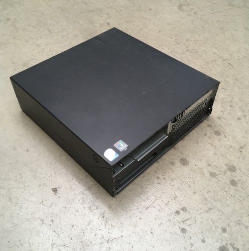
At first glance, just a simple box.
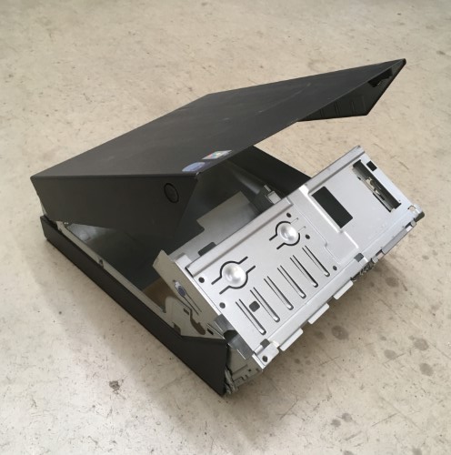
Its apparent simplicity belies an extremely clever design that a lot of people thought long and hard about. It is also a masterclass in metal folding: the sophisticated locking(!) clamshell and double-pivot mechanisms are assembled from stamped and folded parts using only four screws. Very swish.
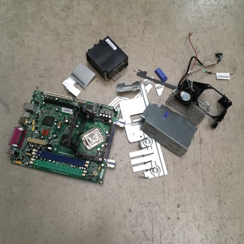
Having extolled the virtues of the Lenovo case I no longer need to feel guilty about cutting it up. Possibly voiding the warranty?
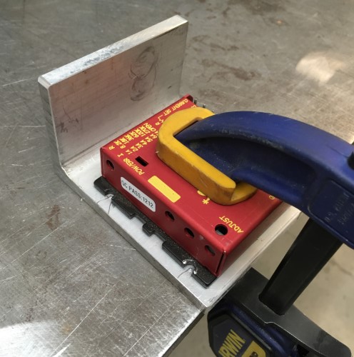
Time to start putting a few new things inside the now empty box. The heart of the controller is the stepper motor driver: a Geckodrive g203V. The literature states that the V stands for Vampire, as in unkillable. I have thus far failed to find the correct mixture of garlic and silver bullets required to prove them wrong. Other than an issue with making them play nicely with some common motion control boards that have a different electronic setup for their step and direction signals, these things are great, if not particularly cheap.
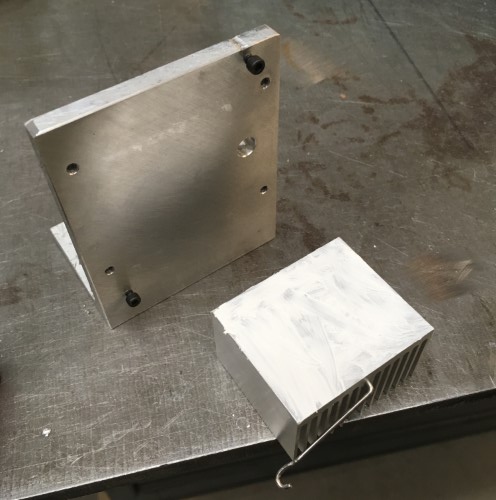
The heat sink from the GPU on the Lenovo motherboard is just the ticket for the stepper motor driver. It has a convenient spring-steel mounting clip that makes it easy to attach it to the opposing face of the motor mount.
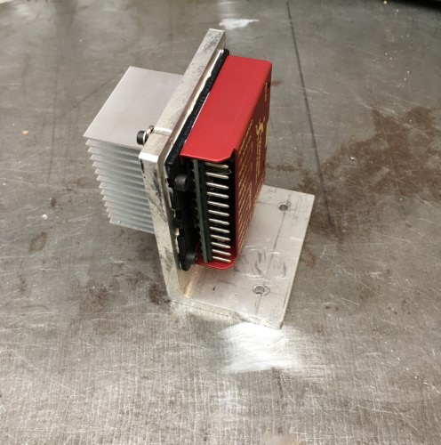
A healthy application of thermal grease on all of the mating surfaces ensures the efficient transfer of heat from the driver to the sink.
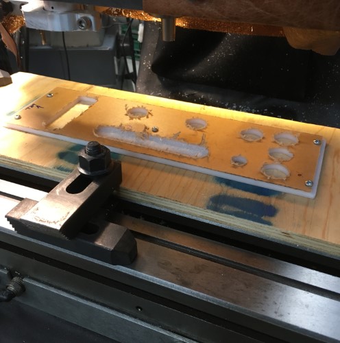
Next, the new Weldcenter needs a face plate for the interface which will be made from a small scrap of 1/4″ acrylic. As usual, drawing up the cutouts and programming the CNC takes substantially longer than the actual cutting. Back surface first: a bunch of holes plus a relief pocket for the rotary pots that are designed for thinner material…
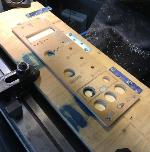
…and the front with engraved text for all of the various buttons, switches, sockets and dials.
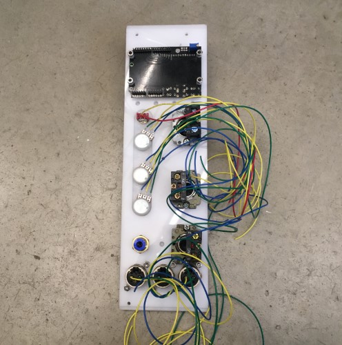
Test fit of all the pre-wired controls including the LCD interface.
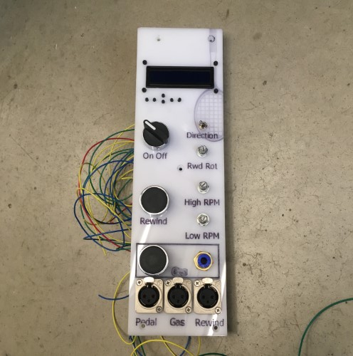
The front side, with residual laser-engraved tennis racket – the acrylic stock is a left-over from a sign project.
There were, of course, a couple of small, but in some cases mildly baffling, errors. The text at the bottom interferes with the mounting screws because I neglected to model them in CAD. Rather more inexplicable is the engraving of the “Gas” text which appears to have been outline, as opposed to single-line, engraved. Don’t know why, nor, as this is strictly a one-off will I spend any more time thinking about it. Much.
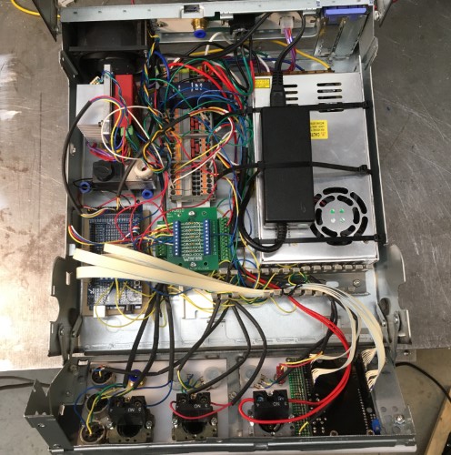
All the various bits and pieces stuffed into the box. Top left: the main cooling fan that used to be at the front of the PC. (For the ultra-observant, now you see why the fins of the heat sink below it are not oriented vertically the way they would be normally). Below the stepper controller is a solenoid for controlling the purge gas. Below that the microcontroller. The middle column is a DIN rail with a small (5 watt) 24 volt DC power supply and a bunch of terminal blocks for connecting everything together. The last column on the right is the other two power supplies. This is a bit of a kluge. There were only supposed to be two flavors of DC in the design: 5 volts for the microprocessor and 24 volts for the solenoid and motor and no fan. However, the 24 volt supply was very bulky so I swapped it for a much more compact 60 volt switching supply. The black box is a dual voltage (5 & 12) supply for an external hard drive of which I have many. So… four flavors: microprocessor 5 volt, fan 12 volt, solenoid 24 volt and stepper motor 60 volt. So much for simplicity. As always, the box is about 25% too small for all the stuff. There should really be cable tracks between each column and along the top and bottom. There aren’t so the resulting wiring is not exactly as neat as it might be.
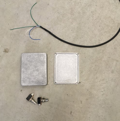
The final piece of the puzzle is a foot control made from a couple of robust momentary switches (the kind used for guitar pedals), a nice metal case (ditto) and some three conductor wire (the extra green wire was spliced on).
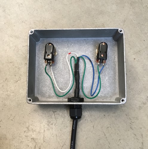
The switches are wired in parallel with their corresponding button on the front panel of the interface. Pressing either the button or the foot switch triggers the control.
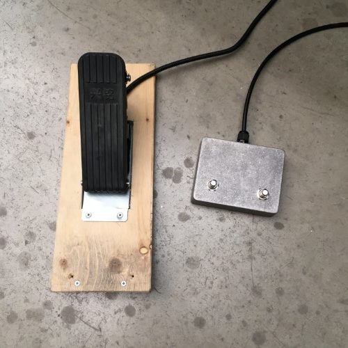
Finished foot controls. The throttle pedal, which is for an electric scooter and cost less than $10 (Canadian, including shipping), is extremely well made.
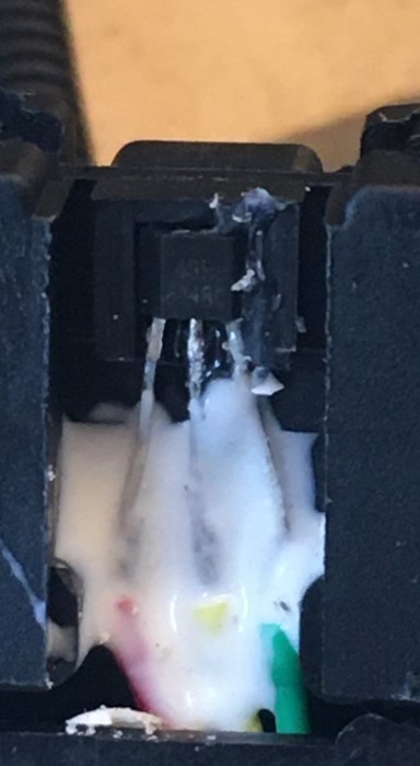
The Hall effect sensor inside it however, (the white stuff is silicon and isn’t as disgusting as it looks), is not. Either I killed it by miss-wiring it briefly while I was hooking everything up, or it was lousy to begin with (I lean towards the latter). Either way, a broken sensor means no throttle pedal which means the entire machine is about as useful as a third shoe. So I replaced the sensor with a brand-name version over-nighted from MagicKy (aka Digi-Key) – (which cost more than the entire pedal after shipping). Hall effect sensors work by measuring the flux of the magnetic field that passes through them. The stronger the magnetic field – i.e. the closer the magnet is to the sensor, the stronger the signal. The silver lining of replacing the sensor with a high quality part is that it has a bigger range – it detects lower strengths of the magnetic field and outputs lower minimum and higher maximum signal voltages, so the pedal response is far more sensitive. Coupled with a pseudo-logarithmic curve which is applied to the output from the sensor in software, the throttle pedal now allows very precise control at the lower end of the speed range where it is most important.
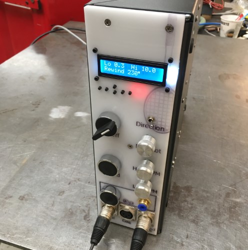
Et voila, the finished LenovoⒸ Weldcenter – running Windows Vista (ok, no it doesn’t).
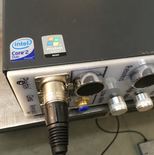
The LED display shows the low and high RPM settings that are mapped to the throttle pedal output. The rewind amount is a fraction of a single rotation at high speed – a tap on the rewind button and the turntable reverses by that amount. In retrospect this turns out to possibly not have been the best way to do this as in practice the amount of rewind required changes too often. At some point I may (or possibly may not) add a mode where the rewind is active while the button/pedal switch is depressed. It also occurred to me too late that I could combine the two foot switches in a single cable and XLR jack, which means that I now have a spare jack for the ion cannon accessory.
A quick test with some scrap tubing before all the kinks with the code were worked out.
