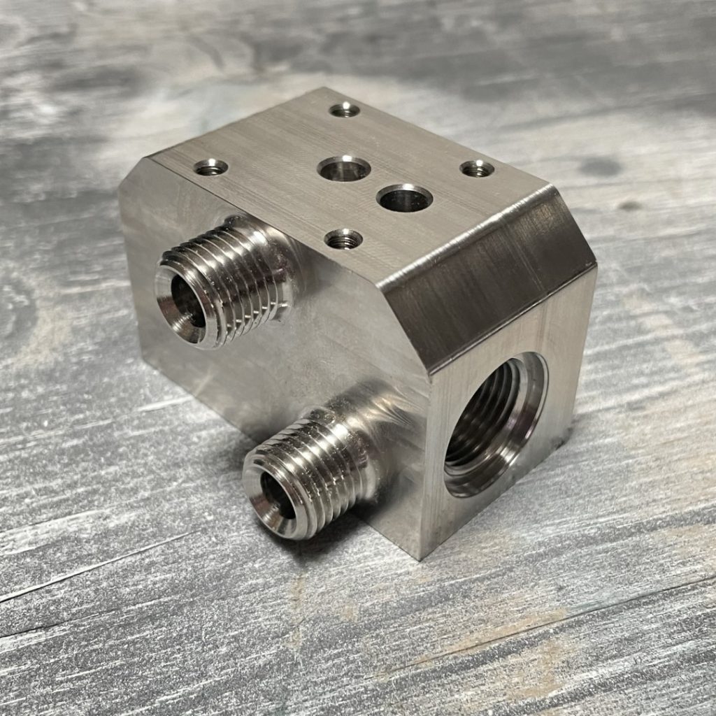
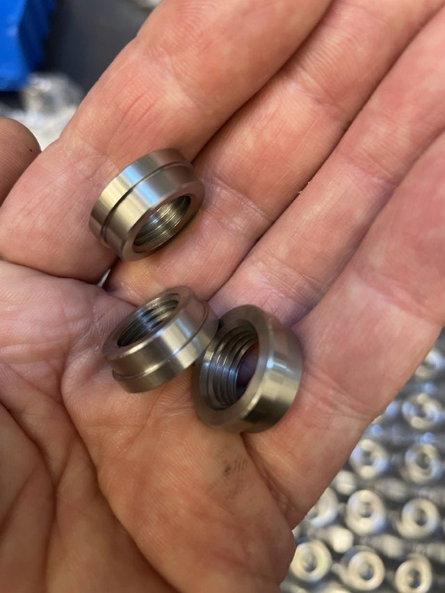
The Lapera Monoblock – a completely redesigned distribution manifold machined from billet 316 stainless steel that integrates the check-valve, supply filter and boiler-fill solenoid. This is an expensive part to make as it involves intricate 3D machining strategies on very expensive CNC equipment. However, it cuts the part count for the manifold by more than half, massively simplifying assembly and replacing sealed-thread connections with the humble, but truly miraculous o-ring (in our opinion one of the wonders of the modern world). This really is a case of less is more, the same only better. The Monoblock – just one of the many improvements you can’t see in the new DS4.
There is nothing particularly wrong with the previous generation composite manifold design, which, with the exception of one custom adapter, is made from off-the-shelf components. But if you need a custom part anyway, why not go the whole nine yards?
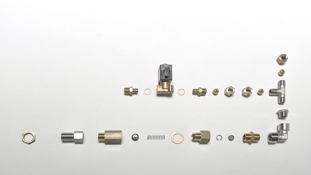
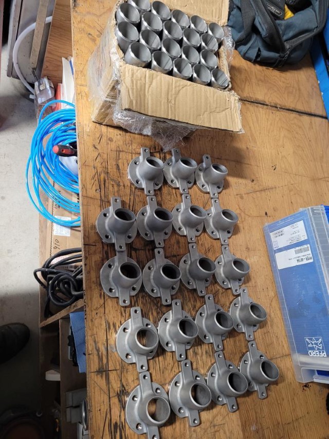
The composite manifold includes an in-line solenoid and has a part count of well over 20. Part count is a bit of a vague term as some “parts”, such as the check-valve are purchased as assemblies and would be replaced as such.
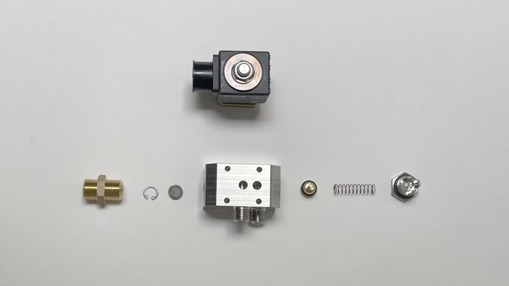
The Monoblock vastly simplifies the assembly, more than halving the “part count”, at the cost of a pair of complex-to-machine parts. It also eliminates two entire plumbing runs.
Worth the trade-off.
Part count is ten – including the o-rings – if you are willing to call the solenoid (which is a complex assembly (but one which you would probably replace as a unit)) a part.
Generally speaking, the composite manifold was a reliable design: because it isn’t directly attached to the boiler, it isn’t subject to large expansions and contractions from the thermal cycling that results from turning the machine on and off; so once assembled and leak free, it tends to stays that way. Getting it that way (not to mention making two extra plumbing runs) was a hassle.
KISS! Keep It Simple Stupid :)
Thanks for reading!
1:
eschew – to avoid habitually especially on moral or practical grounds : SHUN
anfractous – full of windings and intricate turnings : TORTUOUS
dispensation: (a) : the act of dispensing // the dispensation of medication // (b) : something dispensed or distributed // … one of the most remarkable cultural dispensations in the country’s history, the paperback book. — T. E. Cooney //
I haven’t done one of these for a while, but as this bit of machining is part of the set of upgrades for the DS4, the fourth edition of the Lapera DS, that is now shipping, I thought I would go over the whys and the hows in a little detail.
As with all of the modifications for the DS4 (apart from the optional glass cup warmer), and one other that, for dramatic purposes, I’m going to keep under wraps for now, they are invisible from the outside. Up until now, only we would know they are there.
This project is not actually retro machining (which requires the operator to wear white shirts and pocket protectors, flared pants and paisley patterned ties or Nirvana t-shirts depending on the era being replicated). It is, rather, post-machining. Most of the time, the term post-machining refers to material removal operations that are performed on parts from other manufacturing methods: castings, forged or injection molded parts etc. Often however, parts have to be transferred from, say, a lathe, to another machine for secondary operations that can’t be done with that lathe – polishing or wire EDM for example. In this case, we have to put a part that was made with a lathe back on the lathe – which usually means: “we forgot something” or “we changed our minds”. In this case it is because we thought of something new.
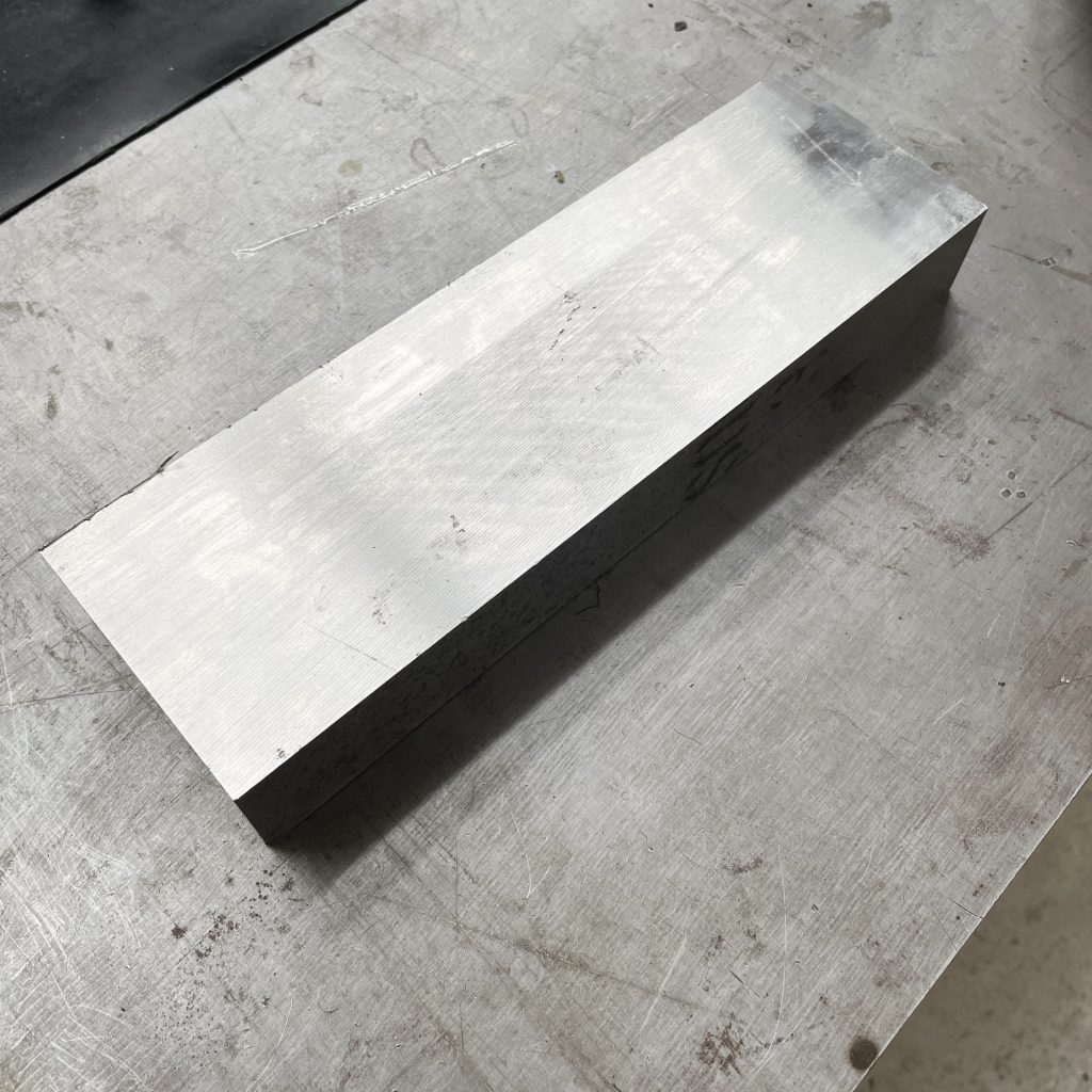
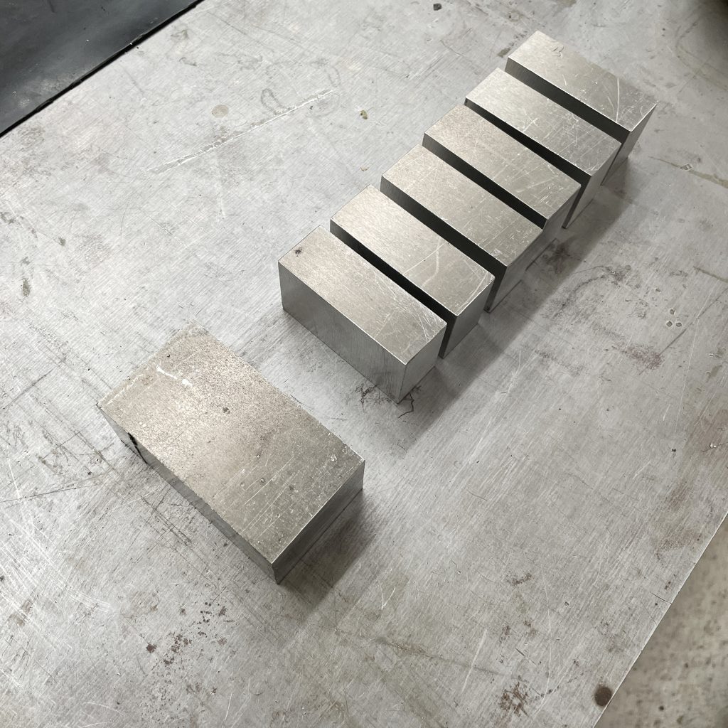
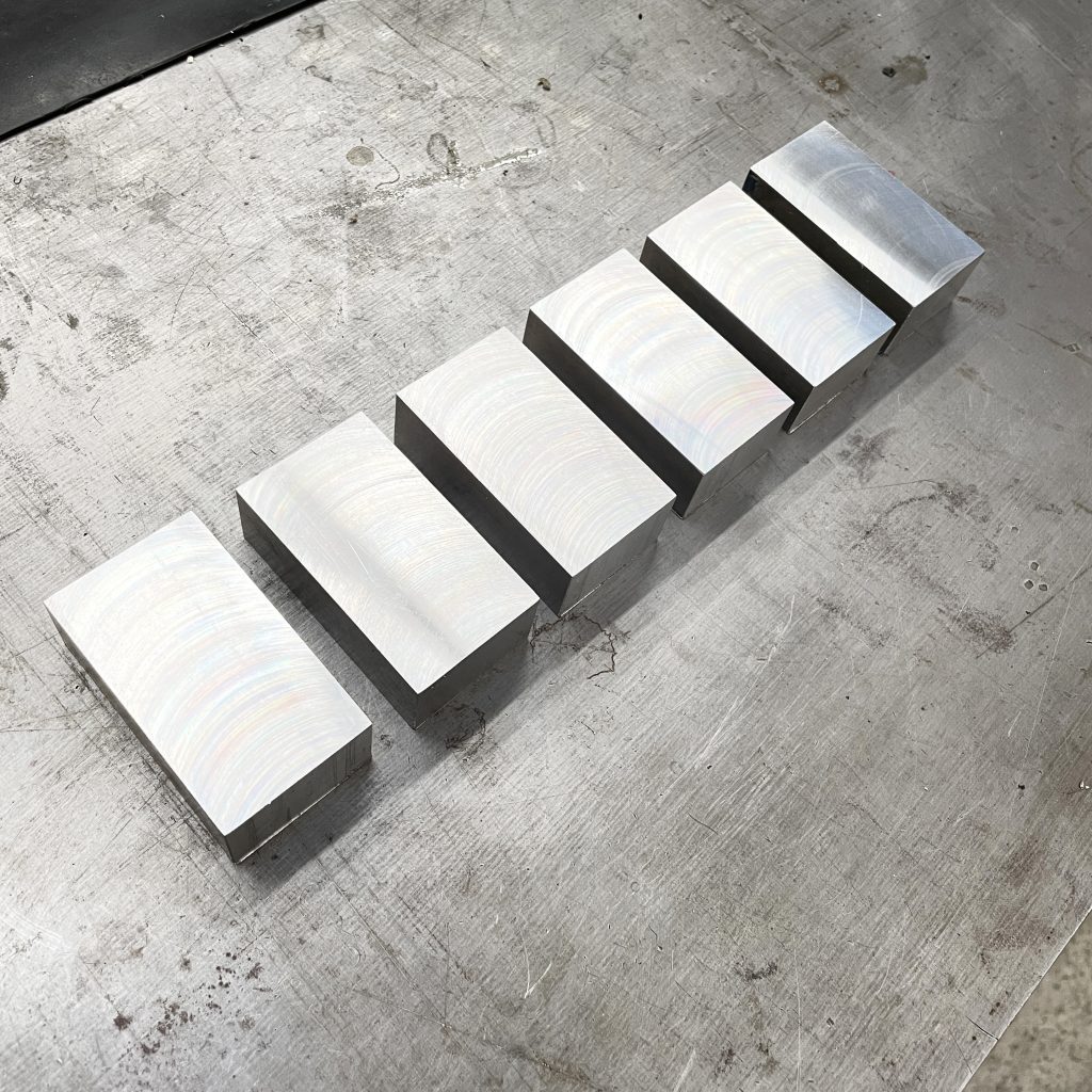
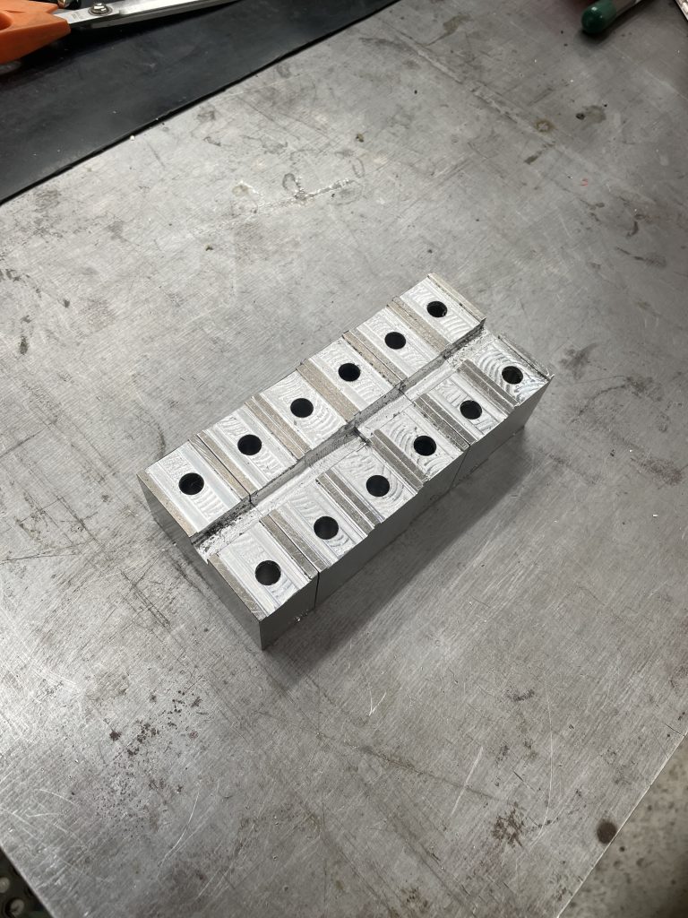
We start, as we often do, with a block of 6061 aluminum, the white bread of machining materials. It would have been more efficient just to have bought the appropriate bar stock, but I was impatient and we had a nice-sized piece in stock that didn’t require too much extra work to rough cut. The majority of the work here is milling the blocks square and to size, so a quarter-hour extra cutting isn’t going to break the bank.
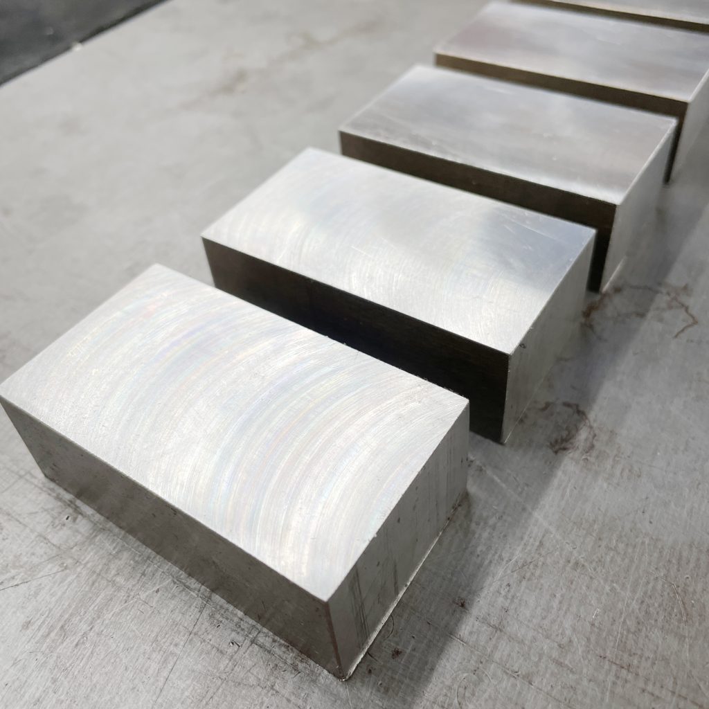
At the end of this particular afternoon’s work, we have six 25x50x69mm blocks (1″x2″x2.75″).
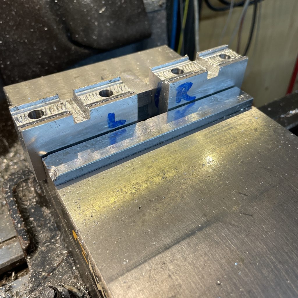
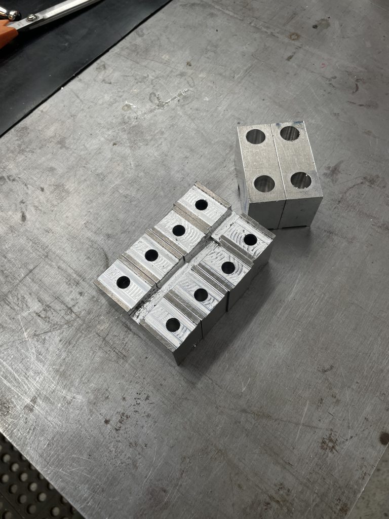
The sized and squared blocks are put in the mill vise against a central positioning stop in pairs to speed up the machining. Roughing and finishing machining strategies using the same tool remove material for a pair of precision-width location slots and some more-of-less-in-the-right-place bolt holes. The parts are flipped for the counterbore machining.
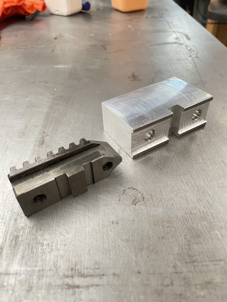
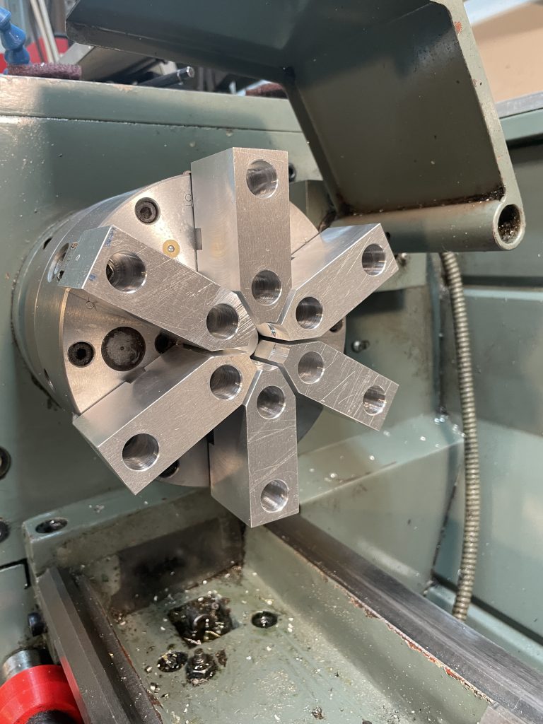
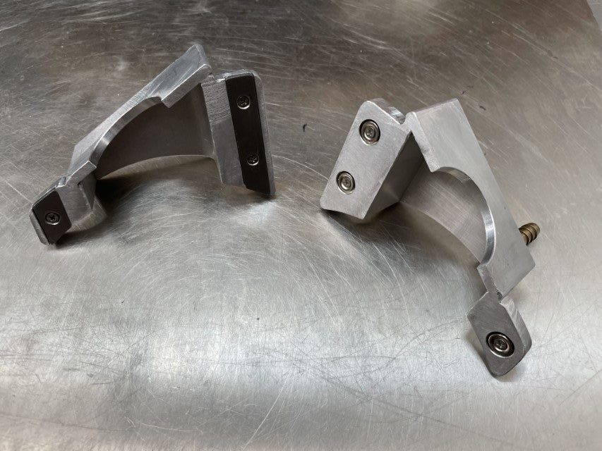
So what’s this all about? The bit on the left is one half of one of the jaws from the six-jaw scroll chuck for the lathe. The scroll is a fascinating mechanism: the teeth of the jaws thread into a spiral groove in the body of the chuck which moves them all radially at the same time. The upside is that all the jaws tighten at the same time – which saves time. The downside is precision. For regular machining where the “part” is contained within the envelope of a larger piece of stock material, it doesn’t really matter much if the center of the stock isn’t exactly aligned with the cutting axis of the lathe. Once you start machining, all of the features will be concentric with the cutting axis.
For post-machining the part needs to be installed as co-axial to the cutting axis as possible if the new features need to be concentric with the original ones. The solution to this is to machine a negative of the part in a set of so-called “soft-jaws”.
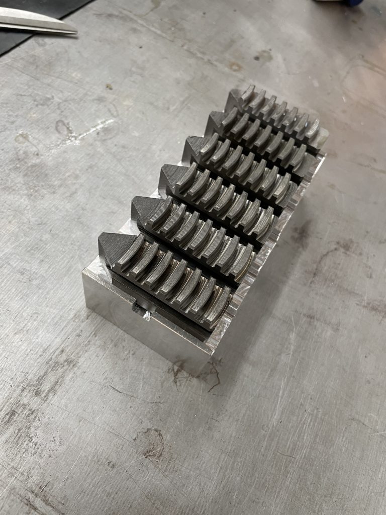
Last pass on the soft jaw machining. Because this isn’t a real CNC lathe that “knows” where the tool is with respect to the part, the process is slightly more arduous: take a bit off, measure, tell the machine where it is, take a bit more, re-measure, tell the machine etc. By the third iteration or so the cut the machine thinks it’s making corresponds to the cut it’s actually making and we can finish the process.
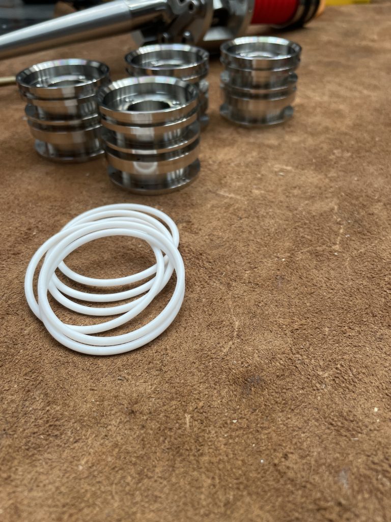
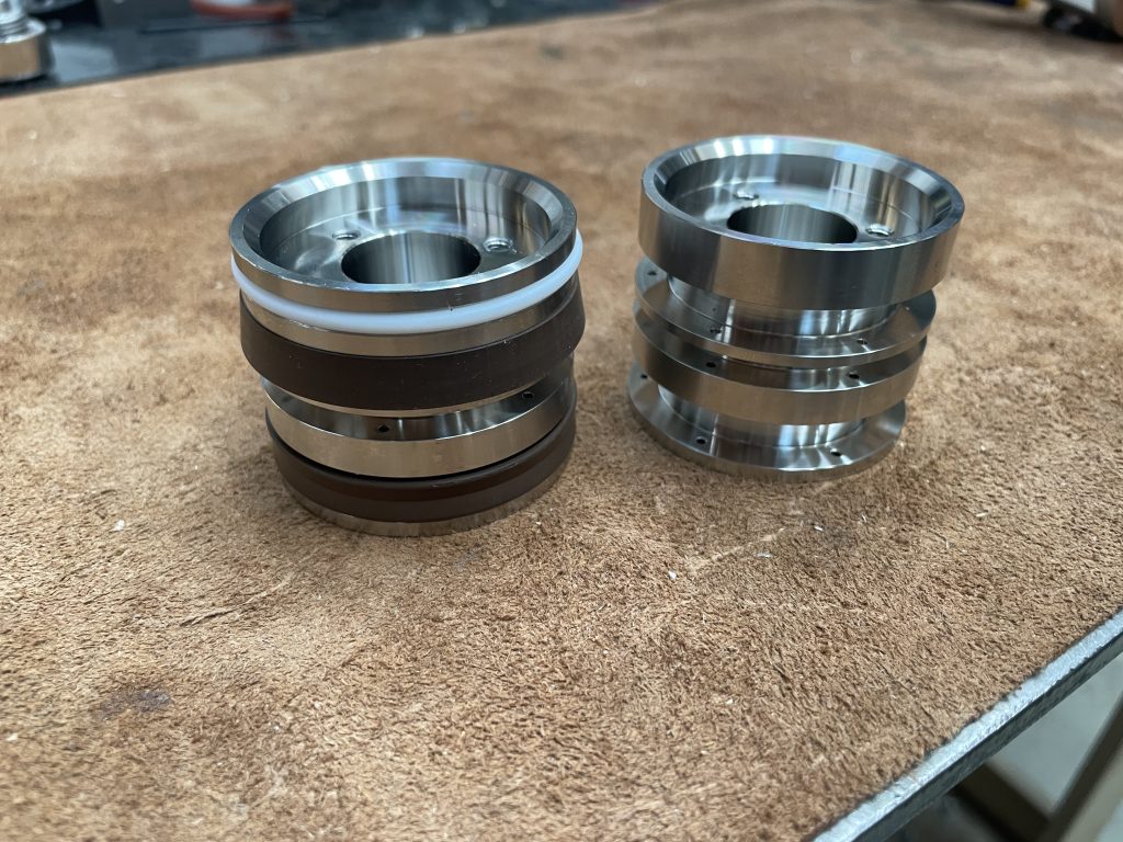
Then we finally get to the why-we’re-doing this bit: machining the actual parts (with our non-dairy coolant). We are cutting a groove in the piston for an o-ring the diameter of which requires a reasonably high tolerance of +/- 60 microns (+/- 0.0024” for inch-folk). That would normally be fairly easy with this lathe, but we also have take into account the added error from re-chucking the part I.e. the fact that it may or may not be in line with the cutting axis. This error, called run-out, is just the “wobble” of the part as it revolves around the cutting axis and, in this case, is about 20 microns (0.0008” or 8 “tenths”). So this increases the tolerance required for the groove to +/- 40 microns.
And why the o-ring? To avoid making a custom part we are using off-the shelf PTFE o-rings as a piston guide bushing for the upper part of the piston. The guide ring keeps the piston centered in the cylinder bore and reduces the load on the seals which means they’ll keep their lubrication for longer – so all this is all in aid of stretching the time between services.
I once watched a documentary about a group of people who had signed up to walk across a bed of coals. You know, the hot, fiery kind that are left after you set fire to a pile of logs – that are perfect for roasting potatoes in tinfoil or a lamb on a spit, but not at all inviting to walk across. Why they were doing this I forget, but it had to be in California some place. Why California? Well, apart from the fact that there was a fire-walking guru involved and everyone was, as far as I recollect, speaking English, where else could it, realistically, have been? The group (no-doubt) consisted predominantly of marketing assistants, soccer moms and at least one dentist seeking deeper meaning or minimally wishing to up their conversational anecdotal game on an extended weekend in the forested foothills of Sonoma County. I have a hazy memory of the guru himself, who was definitely a white guy and (I would like to think) had shoulder-length hair and wore white robes and leather sandals (but more likely cut-off chinos and less-than-white sneakers) but I do distinctly remember the instructions that he gave to his students in their weekend quest to achieve mind over matter: to “think of walking barefoot through an unmown lawn, heavy and wet with pre-dawn dew”, while reciting a mantra of “cool grass” to themselves as they walked, literally, through fire.
Our courageous narrator-participant is an earnest, middlingly charismatic fellow, typical of such pre-reality tv small-D documentaries, professionally mildly sceptical (for dramatic purposes) and possibly somewhat personally concerned (as the barer of the actual feet that would be put in an actual fire at the behest of his producer for our viewing pleasure). We cut from him receiving instruction in-group from the guru to a first-person direct-to-the-camera soliloquy where he voices his doubts about the efficacy of the methodology and wisdom of his career choice. Then, inevitably, we are introduced to the anti-guru: the expert from a renown (but conveniently located) center of higher learning – urban, knowledgeable, dispassionate and, above all else, rational. The scientist brandishes and demonstrates the tools of quantification: temperature probes, human flesh analogs and anatomical foot simulators and rumbles ominously about time-temperature-transformation charts, delta-tees and third degree burns.
The final afternoon of the weekend is taken up with building a twenty-foot long stack of crisply split hardwood logs and in a last meal (or was it a supper?) at a long table facing what is now a large and extremely intense and intimidating fire. It is hot. As the flames die down and the sun begins to set, the group sits in a circle around the guru while they remove their shoes and roll up their pant legs. The fire pit is still radiating a considerable heat – the air shimmers above it and the orange glow it throws off lights the group of rather nervous faces as the final moment draws near. If you have walked bare foot on the beach on a hot, sunny day, you have an idea of what is in store for these would-be firewalkers. Indeed, at this point, faced with the prospect of voluntarily walking into a real fire, a large proportion of the participants get, as it were, cold feet and chicken out. A few brave souls remain, among whom, of course, is our narrator, who is being paid to do this and consequently has no choice. First it is the turn of guru. He walks up to the start of the pit, pauses, presumably in meditation, before walking serenely across the entire length of the fire and stands, seemingly unscathed, at the far end. Then, one by one they line up, and with loud and frequent shouts of “cool grass”, walk extremely briskly or run – like a cat on a hot tin roof – some of the way across the coals before jumping off and plunging their feet into a bucket of cold water. Does our hero make it all the way across? Possibly, I forget. But I do seem to remember the look on his face – triumph mixed with chagrin? – as he, sitting in a lawn chair, and now understandably less interested in narrating for the camera, examines the burns on the soles of his feet.
Why am I telling you this? Well, apart from the fact that the dentist was right: it is a good story, it is, depending on your point of view, a story as much about mind over matter as it is science1. I am certain, from a scientific point of view, that the guru’s feet were just as burnt as our narrator’s and that later, after everyone has gone home, he will be applying the burn cream to his soles, but I am equally certain that at that moment he chose and was able not to feel it.
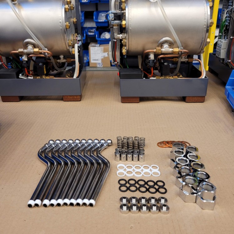
And with that we segue, completely seamlessly, into the actual subject of this post, which is the new steam wand. I could go into the details of what is new, and talk about the “kit” that it replaces that was sold by the (Italian) manufacturer that, for the life of me, I cannot assemble in any way that does not result in hot water and steam escaping energetically from every place it isn’t supposed to, or the quality or rather lack thereof, of the chrome finish which resulted in a least a third failing inspection. Suffice it to say that, with the exception of the wand itself and the two-hole tip, which come from two different manufacturers, everything other than the seals and the spring is made by us. But rather than talk about what is new I would prefer to discuss what is not. Some people have asked why we don’t have one of those silicone or plastic handle thingies on the steam wand so you don’t burn yourself. And my answer is that they are aesthetically displeasing and that I have used machines without them for decades without ever burning myself (badly). Yes, the metal wand gets really hot when you run steam through it. Yes, it will burn your fingers if you hold on to it. So just don’t do that – give it a quick nudge back into place once your done with it and you’ll be fine. I’m with the guru on this one: mind over matter.
1 – and cultural appropriation of (the trappings of) eastern spiritualism by privileged westerners for often philosophically dubious reasons and/or, as in this case, personal gain.
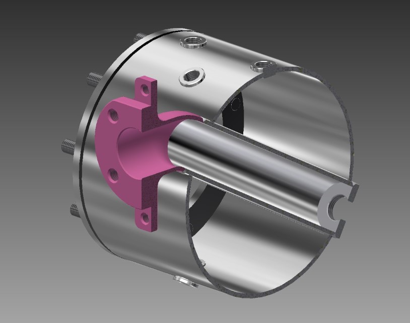
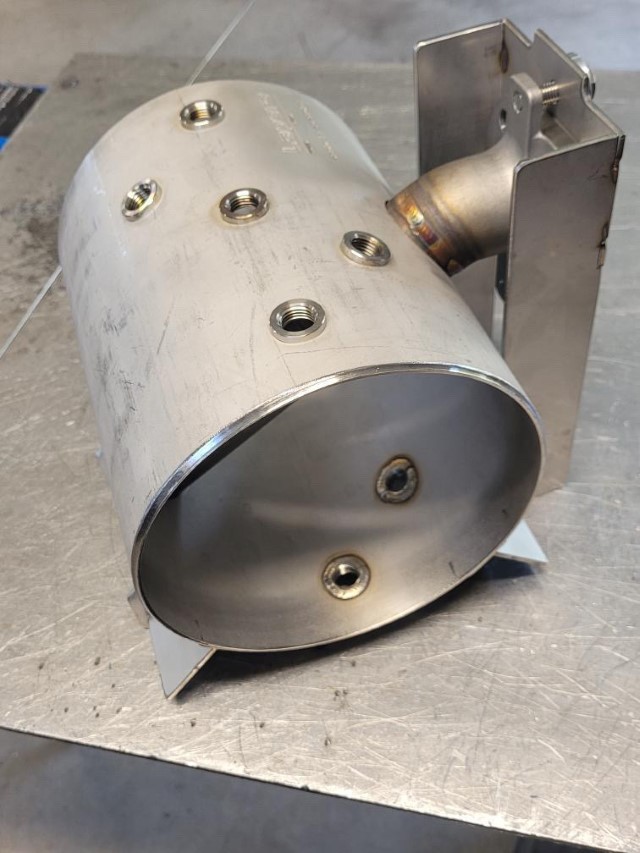
One of the major advantages of the diagonal heat exchanger boiler in the Lapera is that there is a separate water path to the group. This means that the water from the boiler is not used to actually make coffee. If you have ever seen the inside of a well-used boiler, you will know why this is a good thing. The major disadvantage of the diagonal heat exchanger boiler from a fabrication point of view is there is a separate water path to the group. The separate path requires a second chamber that passes through the boiler – a volume that pierces another volume. This means, topologically speaking, that instead of there being just an inside and an outside, there are two insides and one outside – three surfaces that have to be protected simultaneously during welding where they intersect. When welding from the outside things are fairly easy: cover all the holes, fill all the interiors with purge gas and the gas from the torch itself protects the exterior surface. But what if you want weld from the inside (which we do, because it’s waaay better, trust me on this)? One of the solutions is removing all of the oxygen from the room in which the welding is taking place. But this, oddly enough, is not very popular with the people doing the welding. Other solutions require some kind of localized, gas-filled shroud that covers the exterior of the parts being welded. This can be more or less complicated depending on the shape of the parts that are being assembled. The boiler is a bit on the complicated side of the shape scale, so the shrouds, which also have to fit in/around the jig that holds the parts, are a bit, well, tricky.
Cutaway of the boiler – one volume piercing another creating a separate path for fresh water to reach the group. (The casting is (unfortunately) not pink in real life. Were that it were.)
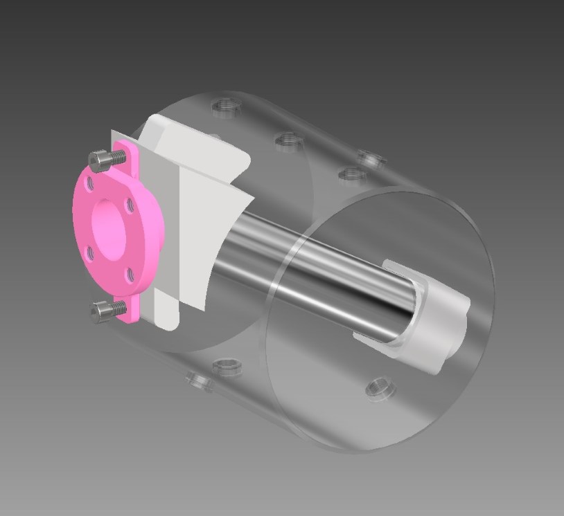
Shrouds in place to protect the outside of the inside of the inside.
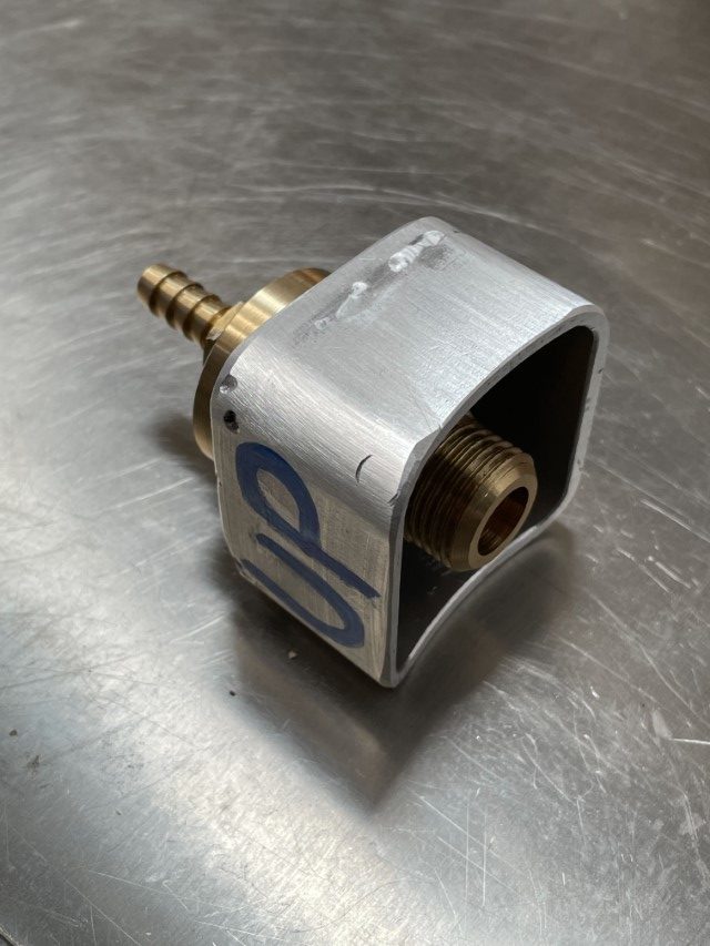
The shroud for the lower end of the heat exchanger (HX) is straightforward-ish. The only minor complication is that the HX tube does not pass exactly through the central axis of the main boiler tube, so the radius cut through the shroud is not quite symmetrical. After welding an end cap onto a small section of square aluminum tubing, the radius cut is easy enough if you have a CNC mill. Which, lucky children that we are, we do.
Quite a few bits of turned and threaded lumps of brass and various adaptors later and, good-enough-for-not-very-close-friends-and-family-whose-company-you-don’t-particularly-enjoy-but-keep-asking-you-to-weld-this-piece-of-their-neighnour’s-friend’s-dishwasher notwithstanding, one lower end purge shroud.
Where things get a little more challenging is at the top end of the HX with the new boiler casting. Both of these purging shrouds, it has to be said, were a bit of an afterthought in that they were thought about after the alignment jig was built. Both of the shrouds could have (and should have) been integrated directly into the jigs themselves. Last time I had my eyes tested, I was shocked to fined out that I don’t have 20-20 foresight.
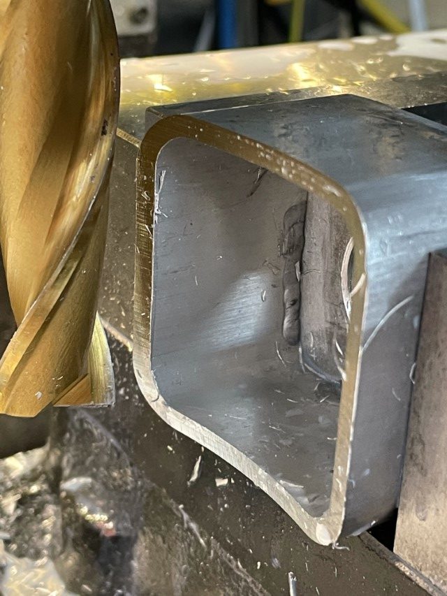
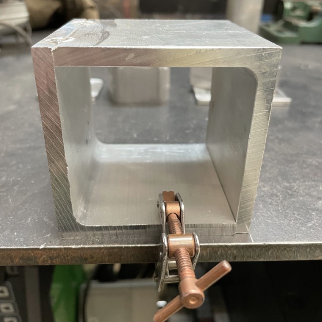
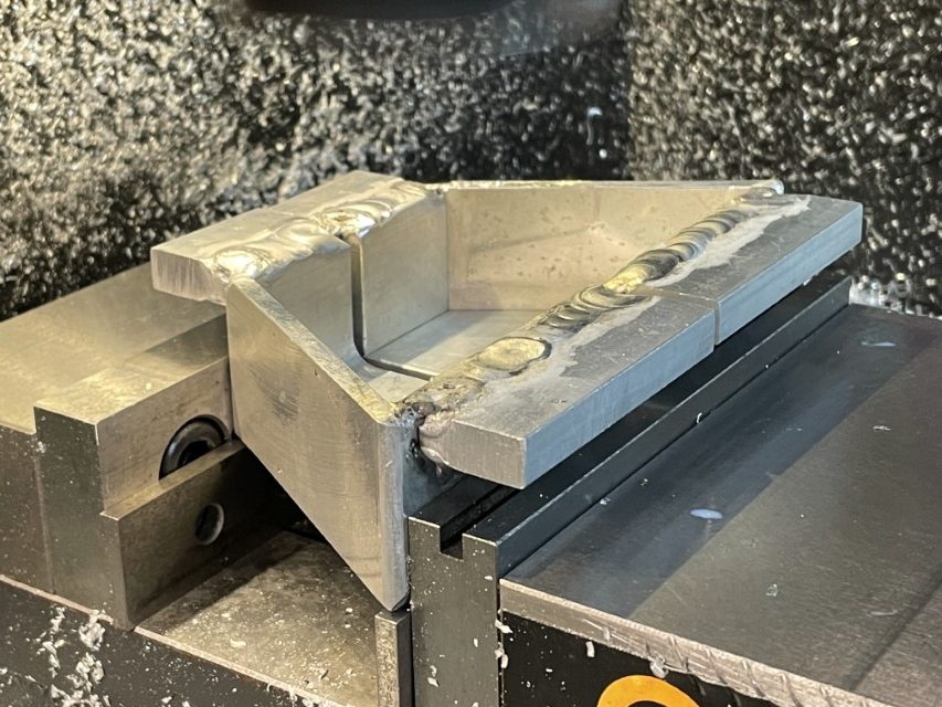
Not having the right size of tubing on hand, I thought it would be quick to weld a few scraps of angle together.
Yeah, well, not so much. I had forgotten just how hard it is to weld aluminum. It took an entire morning of failing to weld with much swearing, vaporizing of electrodes and grinding out of contaminated welds before I remembered that welding aluminum is like going to McDonalds: I go to McDonalds about once every four years in order to remind myself why I don’t go to McDonalds more often. Also akin to a trip to the Scottish restaurant, once it is in the past (and you machine away most of the mess you make) it is just a bad memory.
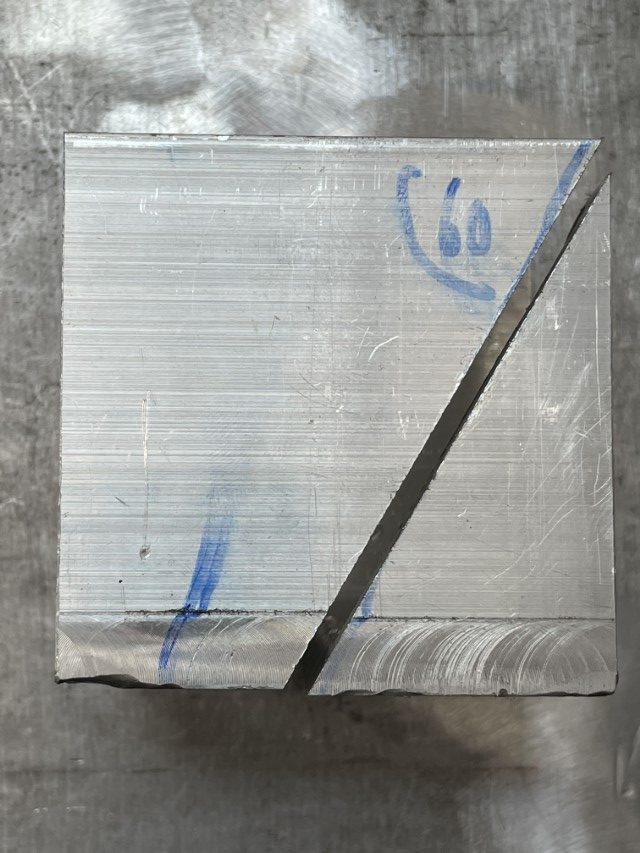
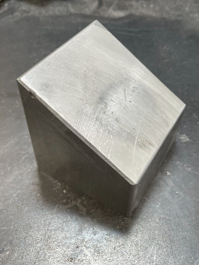
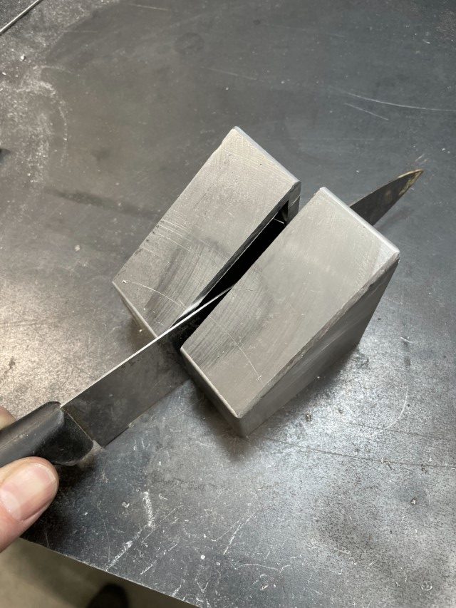
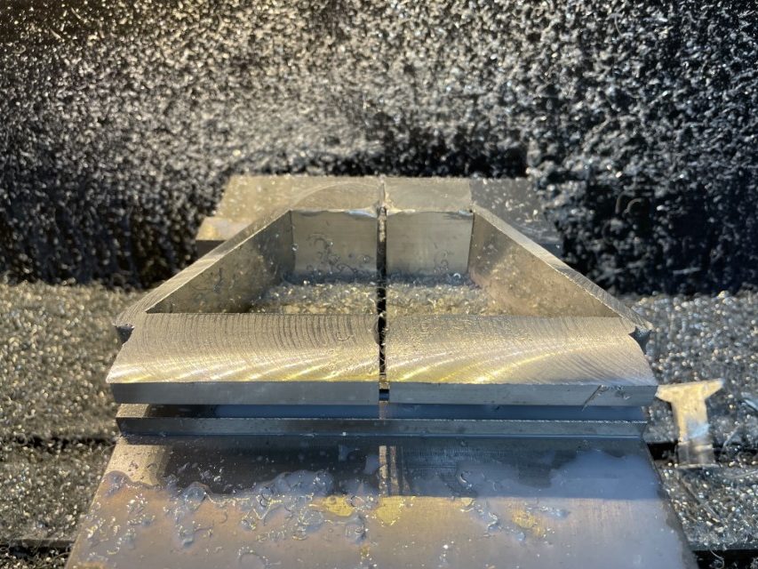
A perfect 60 degree angled cut through the not exactly perfect DIY square tubing.
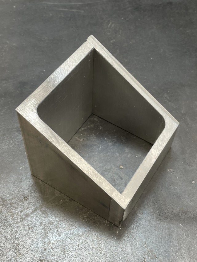
Looks like something. Don’t know what yet. But it definitely needs a cap. Yup.
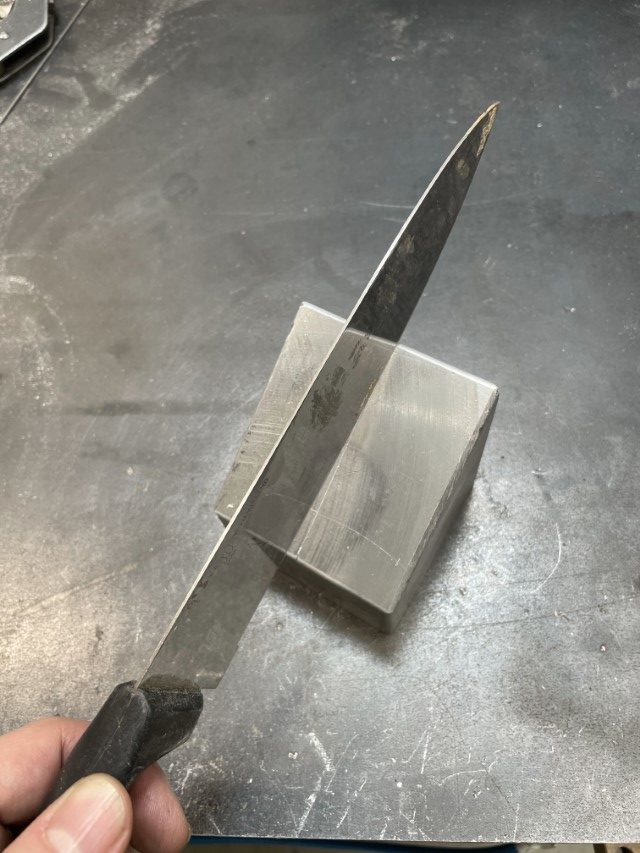
Now we just need a knife.
Sorry……This Old Tony.
And a couple of flanges (close your eyes if you don’t want to be exposed to the welds – but cut me some slack, it is just a jig for Pete’s sake).
As promised, this week’s post is all about jigs (not about jig-jig, despite the title). Well, jigs and purging. When all the parts are finally made, checked, polished, rechecked and sterilized in the autoclave ready for surgery (only mild hyperbole), two more things have to happen before the magic moment when the arc strikes and two pieces of stainless steel become one: they have to held together in the correct alignment and all of the oxygen in the air surrounding the weld location has to displaced or purged – usually with another, inert, gas. This is where jigs and purging come in.
But before we get to the the fancy bits, first some ground-work.
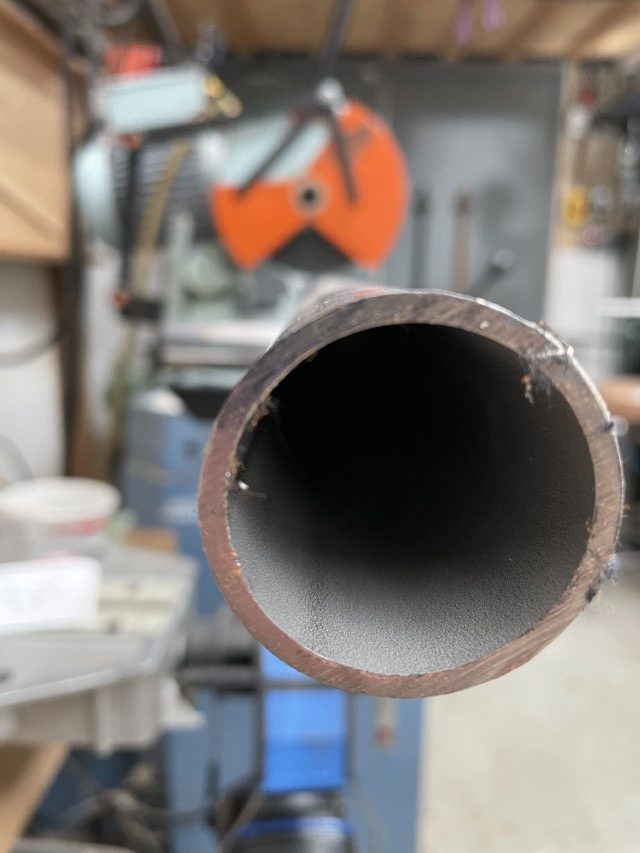
Cutting the stainless tubing to rough length on Soco Xiānshēng. The 3-phase Soco gearhead cold saw, by far the highest quality tool in the building, used to be known as Soco-San but, it turns out, is actually Taiwanese, so this may have been cultural appropriation, inappropriate and/or just wrong. So even though Soco-San sounds better, Soco Xiānshēng it is.
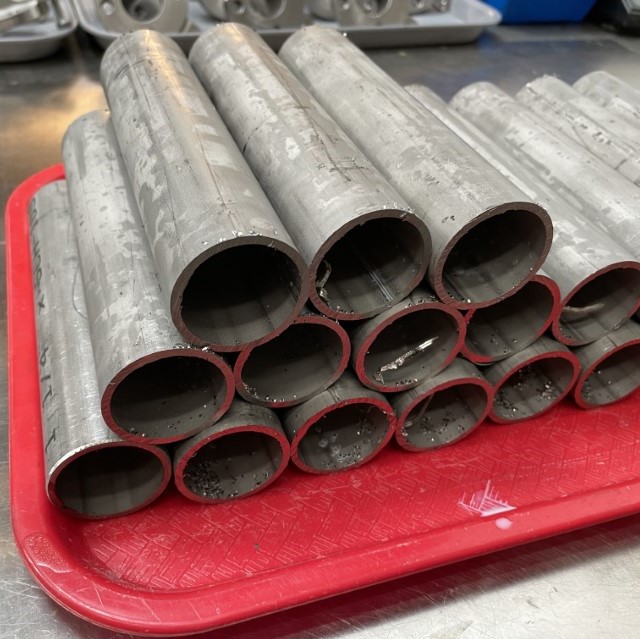
The before: replete with sharp hairy edges, nasty burrs, greasy mill finish, dents and scratches.
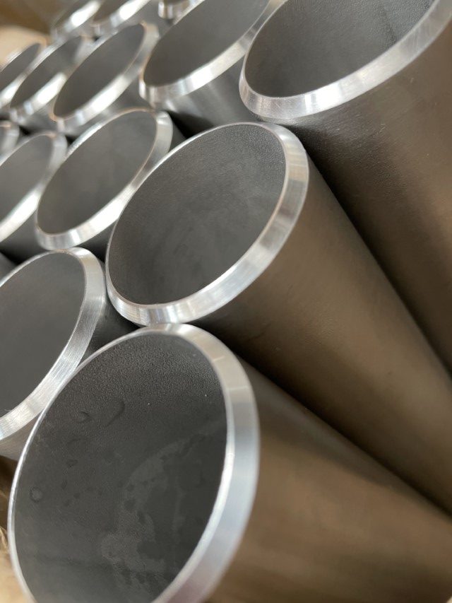
The after: squared and chamfered on the lathe, polished and de-greased to within a nanometer of clean-room cleanliness.
Heat exchanger tubes and flange castings ready on deck.
The first alignment jig ensures that the side-to-side and axial orientation of the tube is correct with respect to the flange casting. Kissing cousins?
Now things start to get a little more elaborate: a dry run with test parts of the heat exchanger (HX) and main boiler tube alignment jig. This setup fixes the depth of the HX through the main boiler tube and ensures that the boiler tube is level and aligned with the bolt pattern on the group flange. Ever-ting gonna be nice’an straight.
So I promised purging as well, but I only got as far as jigs and I am already a day late on my deadline. I’m afraid you’ll just have to come back for more.
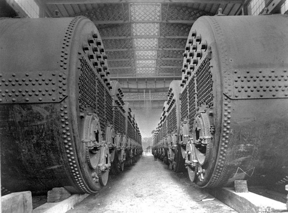
The Titanic, according to my admittedly mildly-unprofessional research, had 24 of these gargantuan boilers, made by Harland & Wolff Shipyard in Belfast (I doff my hat to you and struggle to maintain control of my lower mandible), that collectively consumed 600 tons of coal a day (shoveled by 200 workers!) in order to maintain the ship at cruising speed. 600 tons. I’m gonna say that again: 600 tons. 15 Jumbo Jets. A day. Mind boggling. So to describe the Lapera boiler upgrade as Titanic is a bit of stretch. OTOH, the Titanic’s boilers were only in service for 4 days and 3 hours (if you include the brief period post-iceberg) so we are already well ahead in that regard.
So why a blog post about this? Well, the boiler has undergone a major design revision for the second edition and, as it is by far the most complicated part of the machine and is completely unseen hidden away inside, it deserves a little more narrative-intensive attention and continuity than the Gram can provide. This will require backing up a little so if you have been following the stream there will be a little repetition to allow the narration to catch up with the intervening flow of time (time only going the one way and all that (another corollary of that pesky Second Law of Thermodynamics)).
The biggest and invisibilest upgrade to the boiler is the change from 304 stainless to 316. 316 is generally and significantly superior to 304 in terms of corrosion resistance mostly because it contains a much higher proportion of nickel. The high nickel content makes it quite a bit more expensive than its baby brother. Which may, or may not, be a factor explaining its non-universality in coffee machine boilers. No judgements here. Just saying.
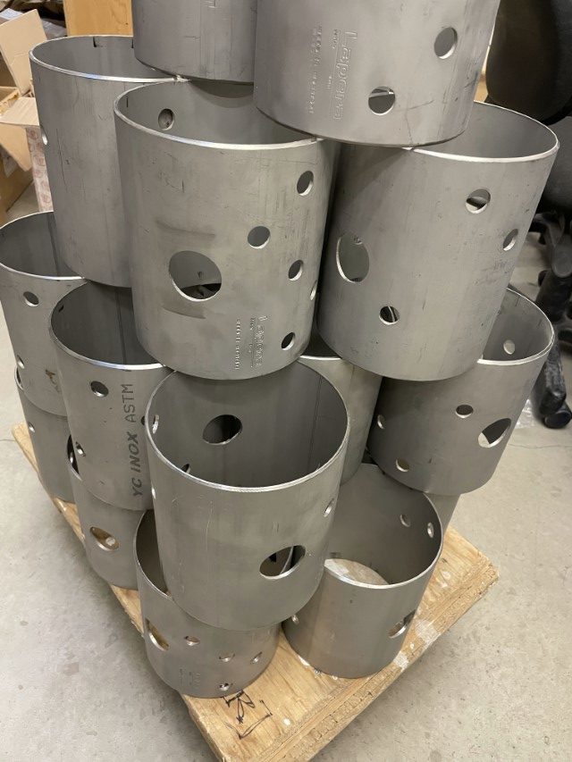
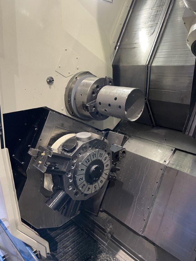
So on to some of the bits and pieces, of which there are a quite a few, that make up the beating heart of the Lapera machine. First up: the main boiler tubes. Cutting these tubes, or rather finding someone to cut them without screwing them up, has been, until recently, the second-greatest problem / source of irritation since the start of this project in 2016; second only in hassle-quotient to the foundry work. Here they are, cut on an completely over-kill bus-sized lathe this time around because I cannot, to save my life, find anyone with a laser tube cutter who will do this correctly. Done also, despite the 500% increase in the price of nickel in March and subsequent collapse/suspension of the London Metals Exchange where all the world’s nickel is traded. (The causes and ramifications of this is a fascinating story btw. At least to me.)
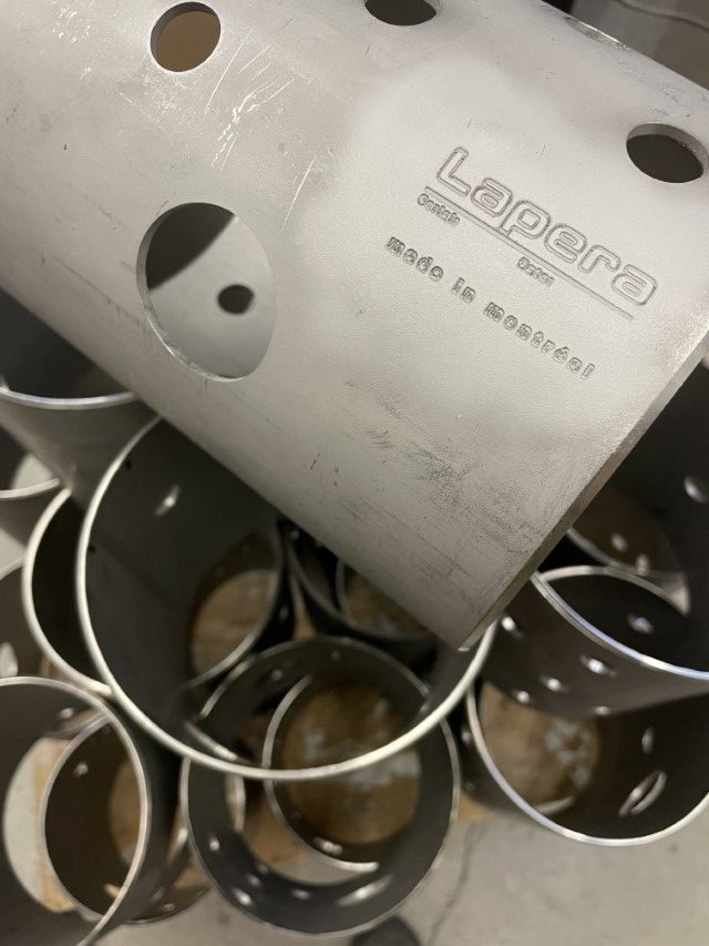
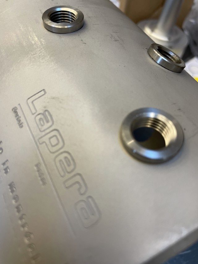
Close-up of the engraved logo. These are a whole other source of complexity as the final appearance of engraving is very dependent on maintaining a consistent depth of cut -which is extremely difficult to do on a solid that deviates at all from its Platonic ideal. This was trivial when the tubes were laser-cut. Don’t get me started.
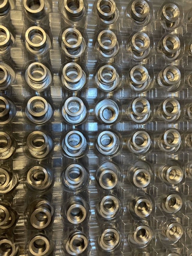
Next but not least are the threaded inserts that are welded into each opening in the boiler wall to provide ports for all the comings and goings of two flavors of water phases. This package contains an infinite number of said inserts, which is surprising because it (ie. the package) fits comfortably on the table.
They seem to fit ;) Who knew?
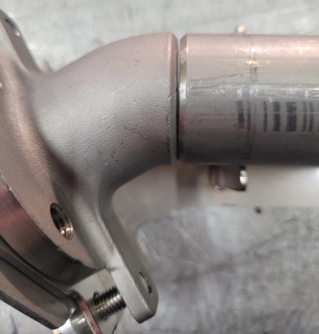
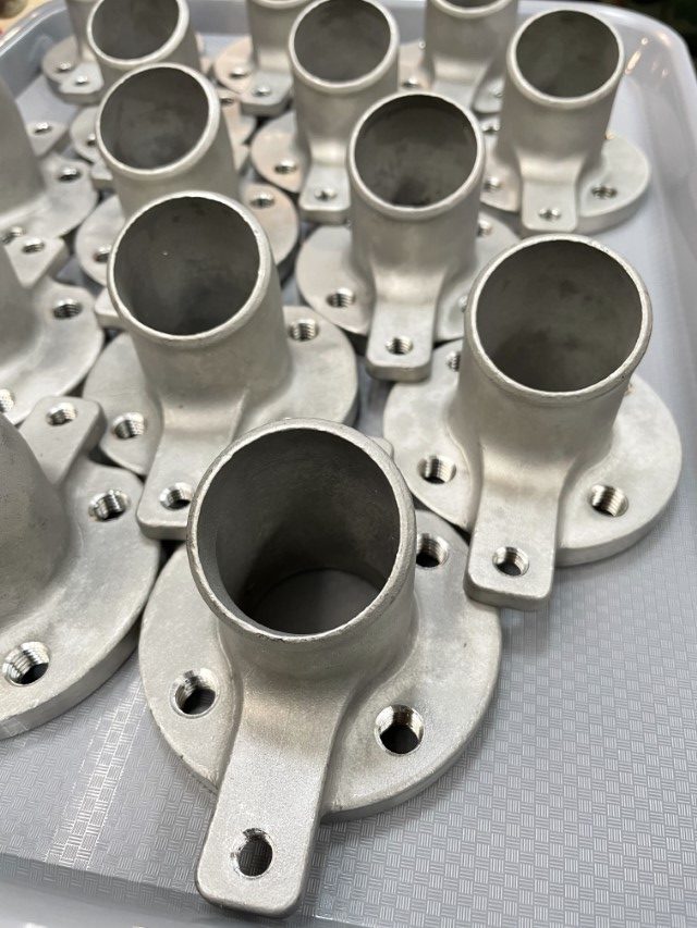
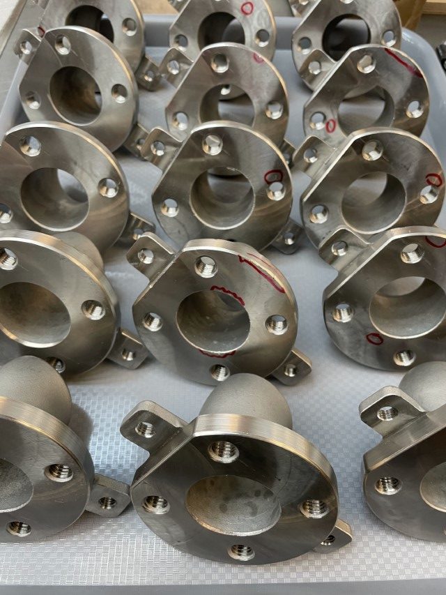
Ok, now that we are more or less caught up. Here is something new (and quite exciting if you are into that kind of thing) to end today’s post: a cast 316 stainless group flange. This casting replaces the original flange that was a built up from individual pieces of sheet metal, all of had to be cut, machined and then welded together. The neck angle is also integrated into the casting which promotes precision of the boiler weldment by a considerable degree. Oh boy, this is soooo much simpler and simpler is soooo much better.
A little QC and a few corrective measures on the all-important flange faces.
The next post will be about jigs and purging I think.
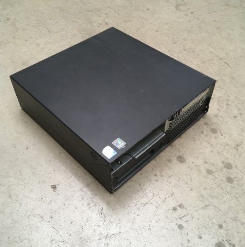
The control components and the wiring for the welding turntable are too delicate to leave exposed to the dust, metal chips and occasional flying tool around the shop. They have to go in a box. I could have drawn one up and had it fabricated along with the rest of the sheet metal parts for the bodywork, but (a) fabrication shops hate/love one-offs and charge accordingly and (b) a recently deceased Lenovo PC (born 2006, died 2019, R.I.P.) seemed like it might fit the bill.
At first glance, just a simple box.
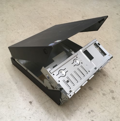
Its apparent simplicity belies an extremely clever design that a lot of people thought long and hard about. It is also a masterclass in metal folding: the sophisticated locking(!) clamshell and double-pivot mechanisms are assembled from stamped and folded parts using only four screws. Very swish.
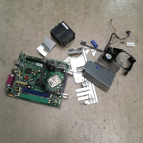
Having extolled the virtues of the Lenovo case I no longer need to feel guilty about cutting it up. Possibly voiding the warranty?
Time to start putting a few new things inside the now empty box. The heart of the controller is the stepper motor driver: a Geckodrive g203V. The literature states that the V stands for Vampire, as in unkillable. I have thus far failed to find the correct mixture of garlic and silver bullets required to prove them wrong. Other than an issue with making them play nicely with some common motion control boards that have a different electronic setup for their step and direction signals, these things are great, if not particularly cheap.
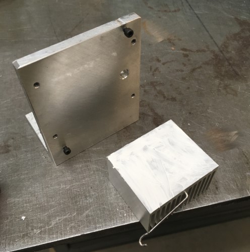
The heat sink from the GPU on the Lenovo motherboard is just the ticket for the stepper motor driver. It has a convenient spring-steel mounting clip that makes it easy to attach it to the opposing face of the motor mount.
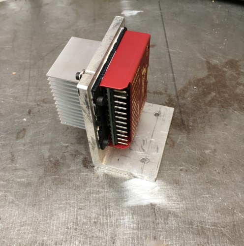
A healthy application of thermal grease on all of the mating surfaces ensures the efficient transfer of heat from the driver to the sink.
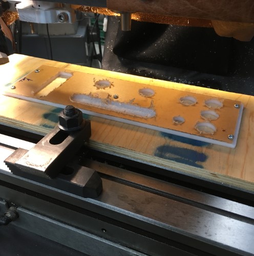
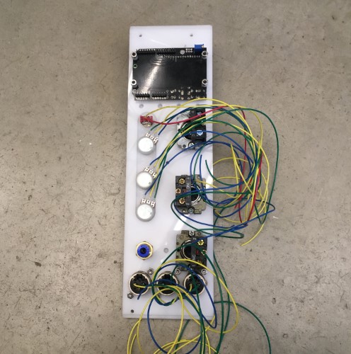
Next, the new Weldcenter needs a face plate for the interface which will be made from a small scrap of 1/4″ acrylic. As usual, drawing up the cutouts and programming the CNC takes substantially longer than the actual cutting. Back surface first: a bunch of holes plus a relief pocket for the rotary pots that are designed for thinner material…
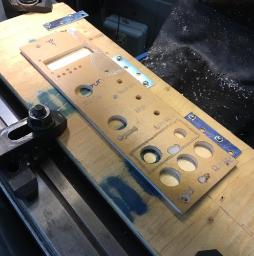
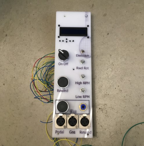
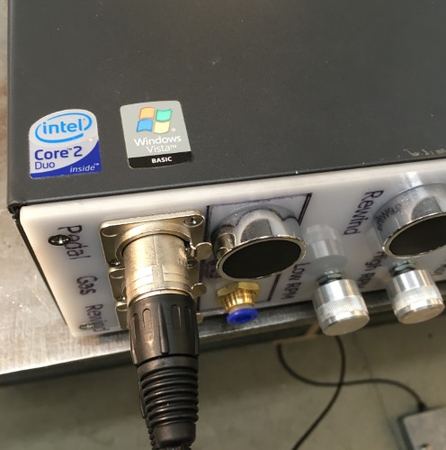
…and the front with engraved text for all of the various buttons, switches, sockets and dials.
Test fit of all the pre-wired controls including the LCD interface.
The front side, with residual laser-engraved tennis racket – the acrylic stock is a left-over from a sign project.
There were, of course, a couple of small, but in some cases mildly baffling, errors. The text at the bottom interferes with the mounting screws because I neglected to model them in CAD. Rather more inexplicable is the engraving of the “Gas” text which appears to have been outline, as opposed to single-line, engraved. Don’t know why, nor, as this is strictly a one-off will I spend any more time thinking about it. Much.
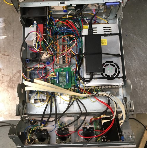
All the various bits and pieces stuffed into the box. Top left: the main cooling fan that used to be at the front of the PC. (For the ultra-observant, now you see why the fins of the heat sink below it are not oriented vertically the way they would be normally). Below the stepper controller is a solenoid for controlling the purge gas. Below that the microcontroller. The middle column is a DIN rail with a small (5 watt) 24 volt DC power supply and a bunch of terminal blocks for connecting everything together. The last column on the right is the other two power supplies. This is a bit of a kluge. There were only supposed to be two flavors of DC in the design: 5 volts for the microprocessor and 24 volts for the solenoid and motor and no fan. However, the 24 volt supply was very bulky so I swapped it for a much more compact 60 volt switching supply. The black box is a dual voltage (5 & 12) supply for an external hard drive of which I have many. So… four flavors: microprocessor 5 volt, fan 12 volt, solenoid 24 volt and stepper motor 60 volt. So much for simplicity. As always, the box is about 25% too small for all the stuff. There should really be cable tracks between each column and along the top and bottom. There aren’t so the resulting wiring is not exactly as neat as it might be.
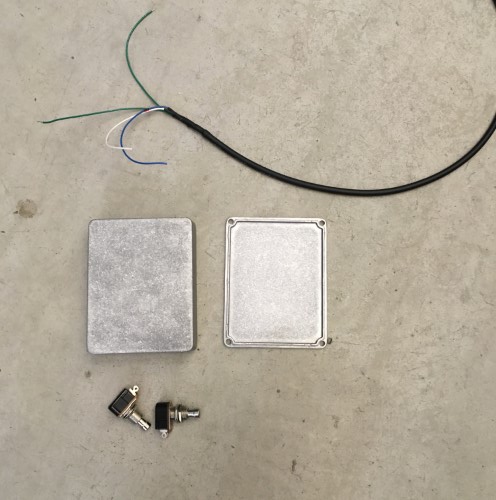
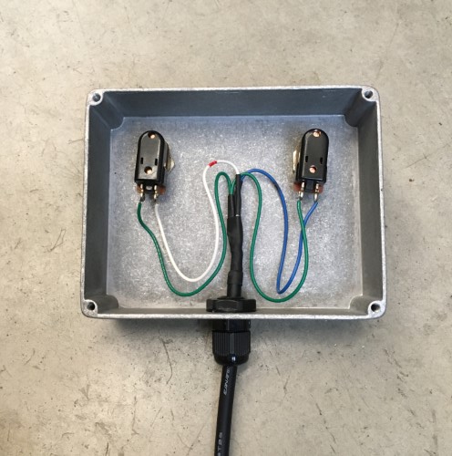
The final piece of the puzzle is a foot control made from a couple of robust momentary switches (the kind used for guitar pedals), a nice metal case (ditto) and some three conductor wire (the extra green wire was spliced on).
The switches are wired in parallel with their corresponding button on the front panel of the interface. Pressing either the button or the foot switch triggers the control.
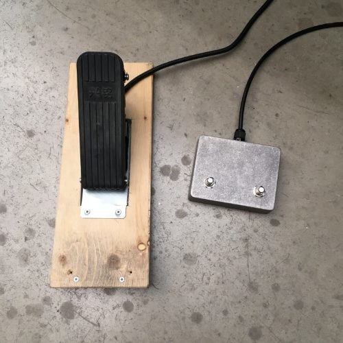
Finished foot controls. The throttle pedal, which is for an electric scooter and cost less than $10 (Canadian, including shipping), is extremely well made.
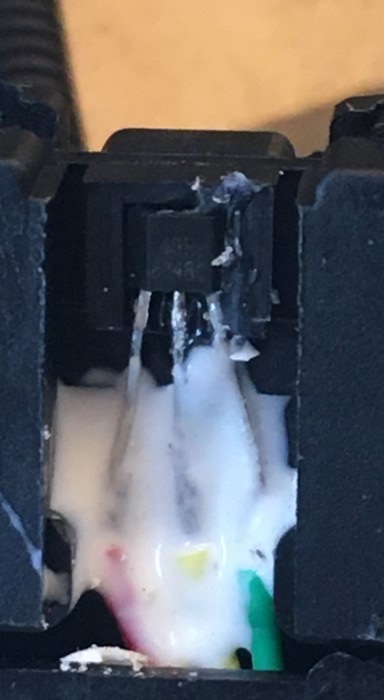
The Hall effect sensor inside it however, (the white stuff is silicon and isn’t as disgusting as it looks), is not. Either I killed it by miss-wiring it briefly while I was hooking everything up, or it was lousy to begin with (I lean towards the latter). Either way, a broken sensor means no throttle pedal which means the entire machine is about as useful as a third shoe. So I replaced the sensor with a brand-name version over-nighted from MagicKy (aka Digi-Key) – (which cost more than the entire pedal after shipping). Hall effect sensors work by measuring the flux of the magnetic field that passes through them. The stronger the magnetic field – i.e. the closer the magnet is to the sensor, the stronger the signal. The silver lining of replacing the sensor with a high quality part is that it has a bigger range – it detects lower strengths of the magnetic field and outputs lower minimum and higher maximum signal voltages, so the pedal response is far more sensitive. Coupled with a pseudo-logarithmic curve which is applied to the output from the sensor in software, the throttle pedal now allows very precise control at the lower end of the speed range where it is most important.
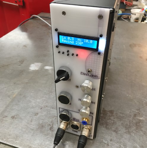
Et voila, the finished LenovoⒸ Weldcenter – running Windows Vista (ok, no it doesn’t).
The LED display shows the low and high RPM settings that are mapped to the throttle pedal output. The rewind amount is a fraction of a single rotation at high speed – a tap on the rewind button and the turntable reverses by that amount. In retrospect this turns out to possibly not have been the best way to do this as in practice the amount of rewind required changes too often. At some point I may (or possibly may not) add a mode where the rewind is active while the button/pedal switch is depressed. It also occurred to me too late that I could combine the two foot switches in a single cable and XLR jack, which means that I now have a spare jack for the ion cannon accessory.
A quick test with some scrap tubing before all the kinks with the code were worked out.