Posted on 1 Comment

Goldilocks part 3

The set of the bears. Plate 7, 1664, by Marcus de Bye, after Marcus Gheeraerts I, 1559. Gift of Bishop Monrad, 1869. Te Papa (1869-0001-67)

Though I’ve run out of three bears analogies, I’ve stuck with the story’s structure: first the porridge was too hot, then it was too cold, and finally Goldilocks found one that was just right. This iteration of the HX caused me to take my hat off, yet again, to the Italians. Many months ago, Dr. Pootoogoo brought a boiler from a later-model Brugnetti to my studio. The flange bolts were so badly rusted that it wasn’t ever going to go back into service without replacing them. It happened to be one with a diagonal HX that I hadn’t examined before and it inspired my to try a similar concept with the horseshoe HX prototype. I was quite surprised that the 60ml HX (baby bear) didn’t deliver water that was cooler than the brew reservoir temperature even though the HX volume was close to the 50ml shot volume. I also started thinking about what the ‘correct’ temperature for the brew reservoir should be. It occurred to me it might not be the best thing for it always to be the same. For example: if the group is at 75 C and the water coming in is at 102 C, the resultant water temperature at the puck is 92 C (these are roughly the numbers for both vintage machines) and we know that the group gains heat after a shot, let’s say for the sake of argument it gains 3 degrees and requires about 2 minutes per degree to recover i.e. 6 minutes. It follows then that for the next shot, if it is to be pulled [i]before the end of the recovery time,[/i] it would be preferable to have the brew reservoir water at a lower temperature than 102 degrees so that when it reaches the puck it will be at same magic 92 degrees. Because of the difference in thermal properties of the materials (i.e. the brass group and the water) and their relative volumes (i.e. big thermal mass of brass vs 50ml of water) it isn’t a one to one relationship. But it is linear – i.e. it will be a constant times the temperature rise of the group. So at any given time during group recovery, the required brew reservoir temperature is the reservoir idle temperature minus the group temperature rise times some constant. In math not English:

Tbr = Tbr_idle – K(Tgroup – Tgroup_idle)

In other words if the heat gain curve of the group could be inversely mirrored by the brew reservoir, then water will be at the right temperature when it reaches the puck [i]no matter when it is pulled[/i]. This is really just destructive wave interference:

If the brew reservoir temperature curve is positive (i.e. there is heat gain), then it will compound the problem of heat gain at the group. But if the brew reservoir temperature drops after a shot, then it will compensate.

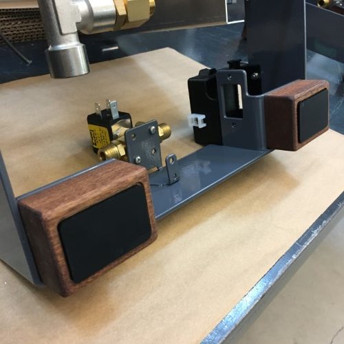
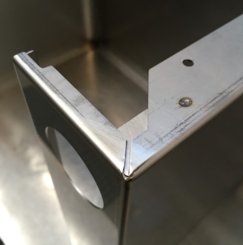
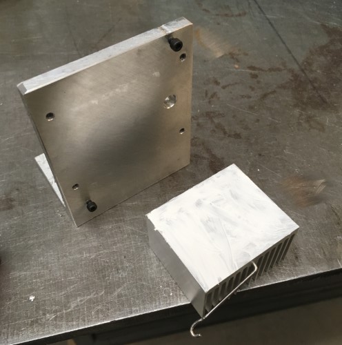
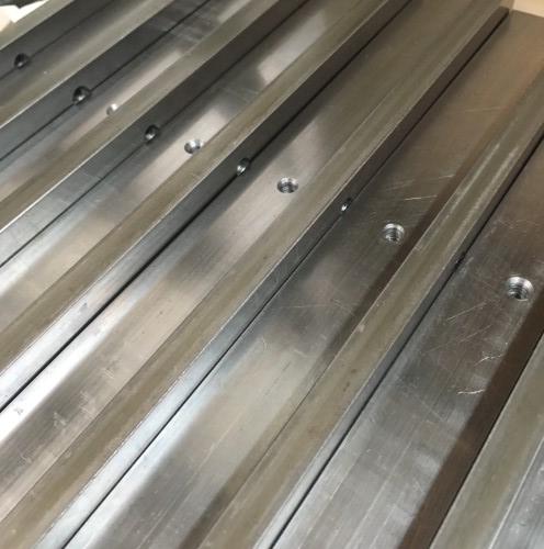
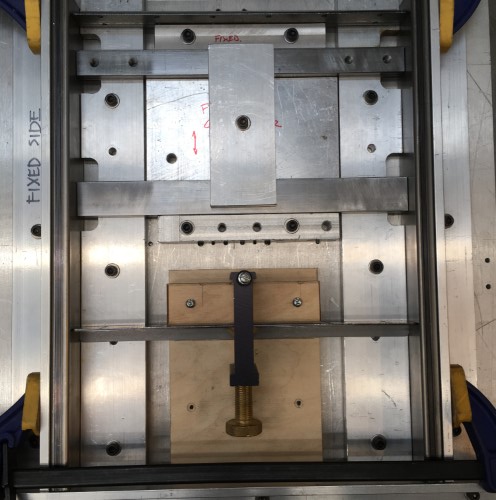
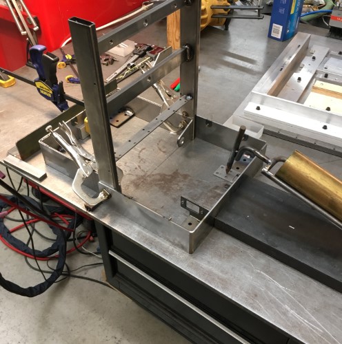
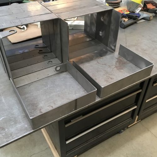
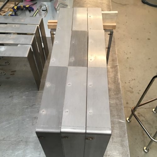
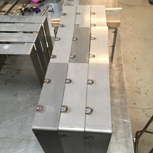
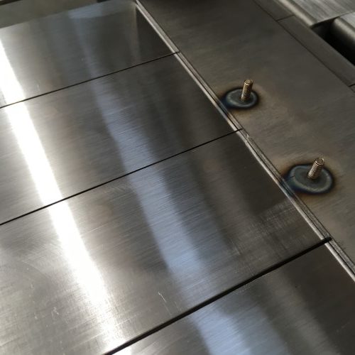
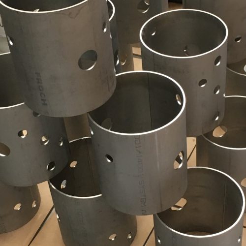
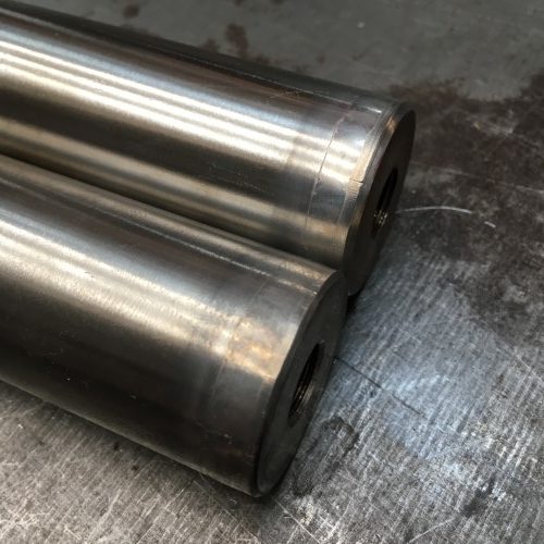
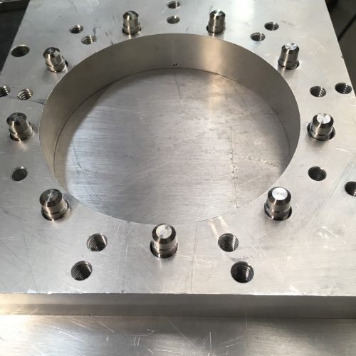
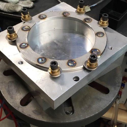
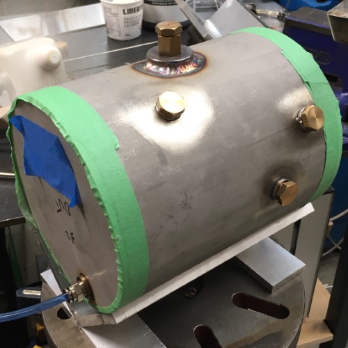
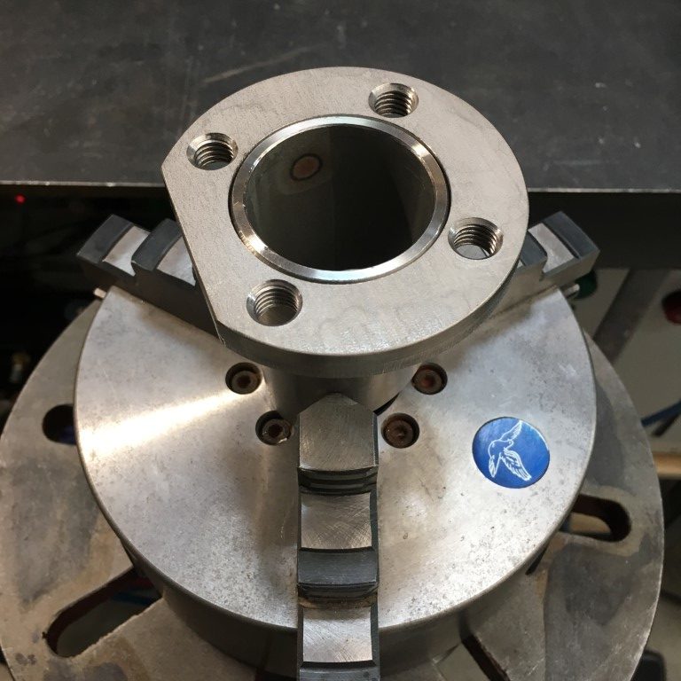
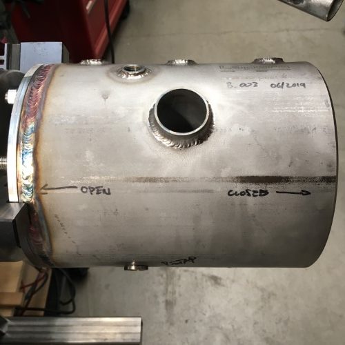
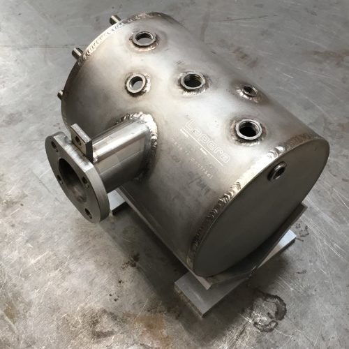
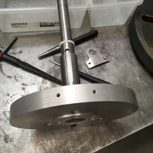
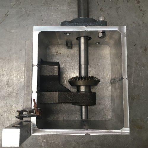
The diagonal HX design consists of a large diameter pipe which connects directly to the back of the brew reservoir – essentially increasing the volume of the brew reservoir four-fold. In fact, the concept of the brew reservoir is pretty much gone altogether in this design – the group flange actually becomes one end of the heat-exchanger. A small diameter injector tube runs through the middle of the large diagonal pipe. Line water comes in through the injector too fast for the surrounding water to heat it to boiler temperature and mixes with the water behind the group to get the really stable results that we saw in the earlier testing.

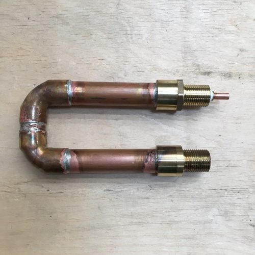
I replicated the basic principal minus the diagonal tube and in so doing figured out why the diagonal design ended up that way i.e. diagonal.

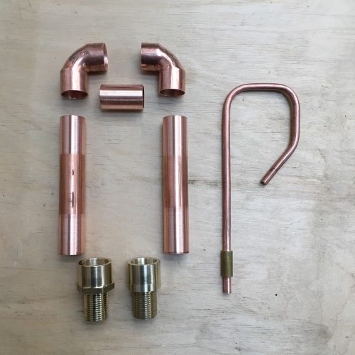
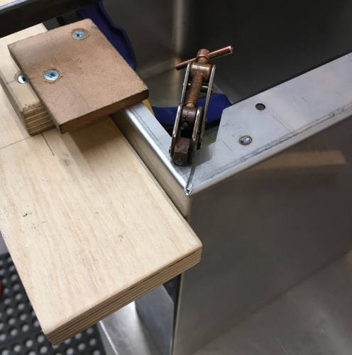
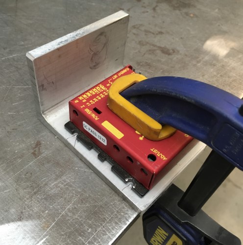
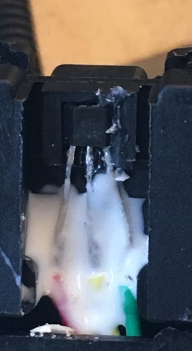
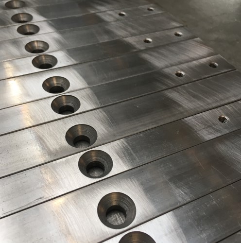
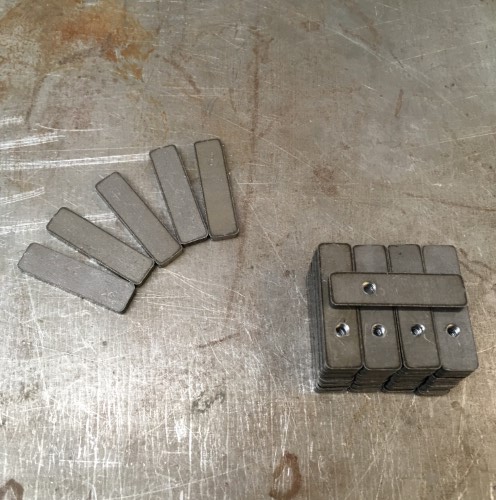
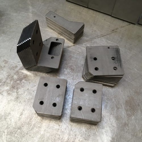
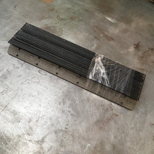
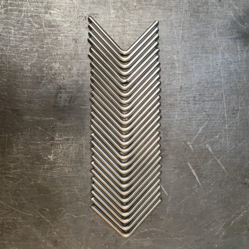
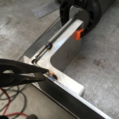
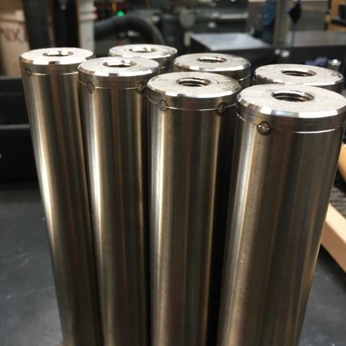
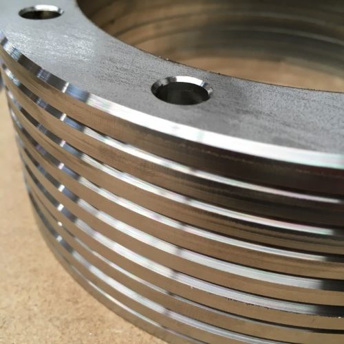
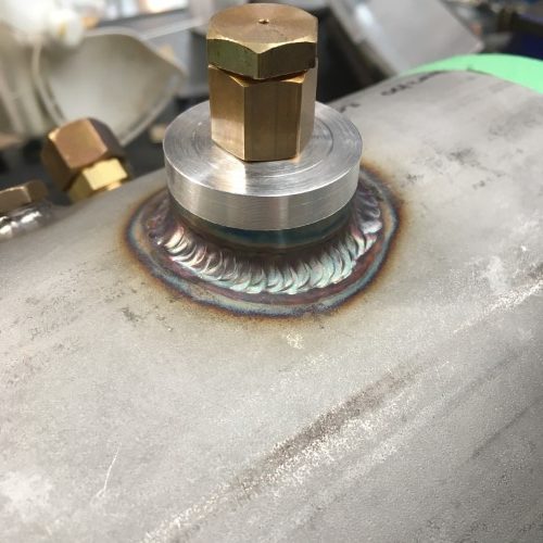
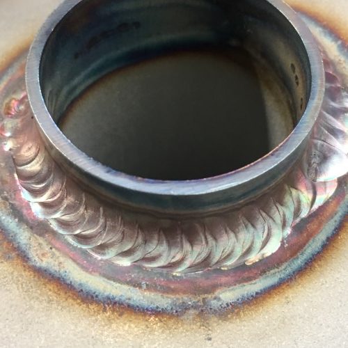
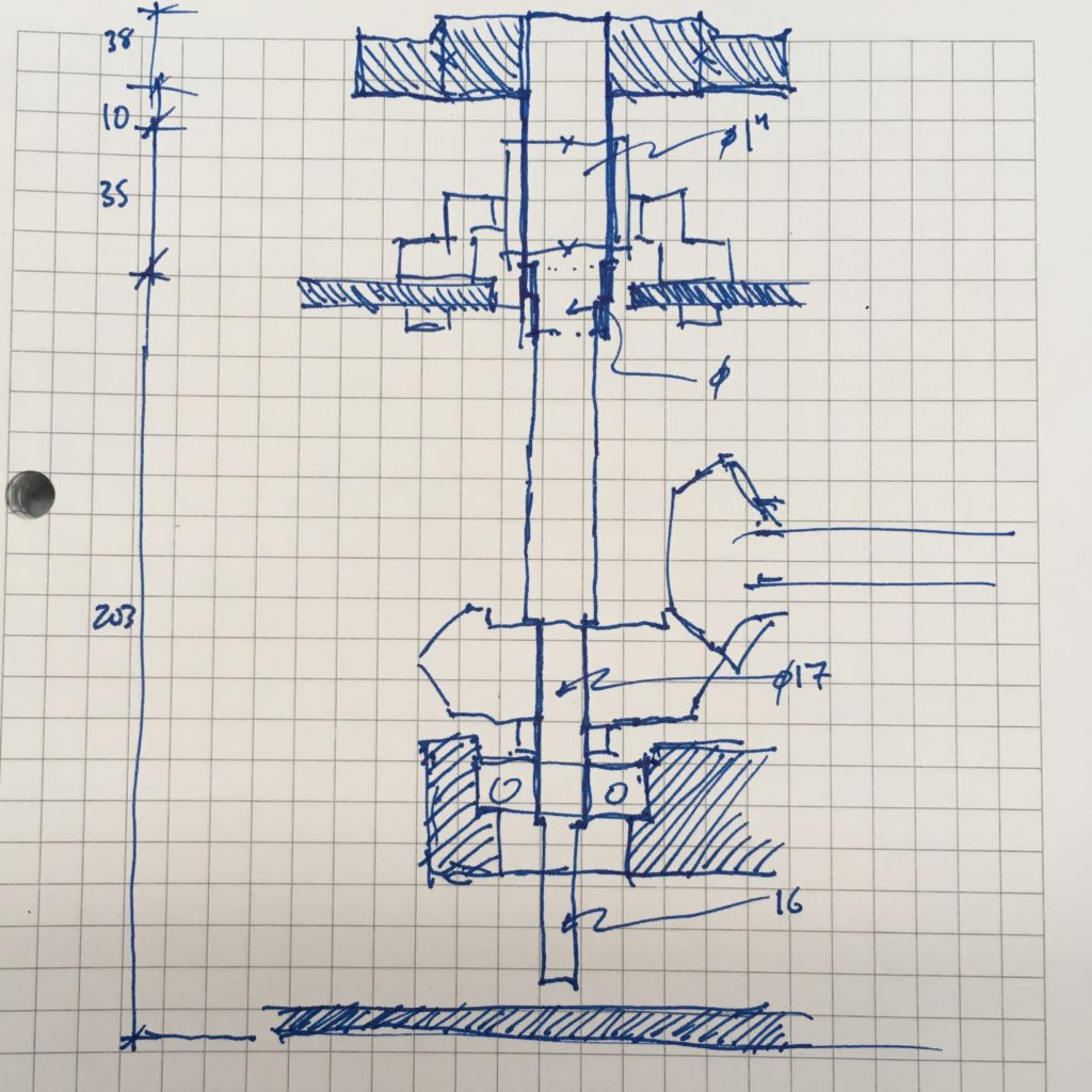
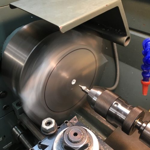
The last kink in the 6mm tubing was only way to thread all the larger diameter fittings onto the injector. And this is a one-way operation: once it is brazed together you can’t take it apart again.

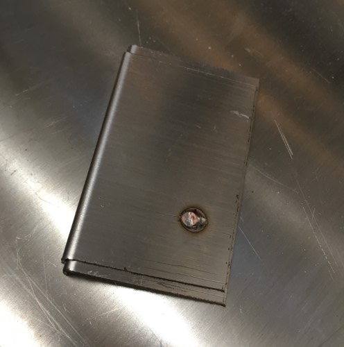
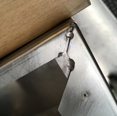
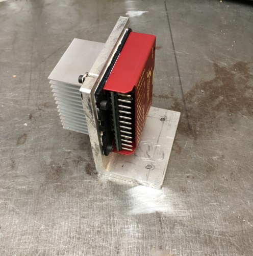
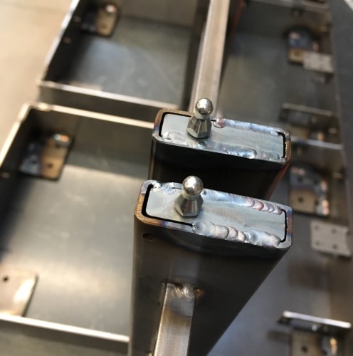
Brazed and (sort-of) cleaned.

And here are the results:
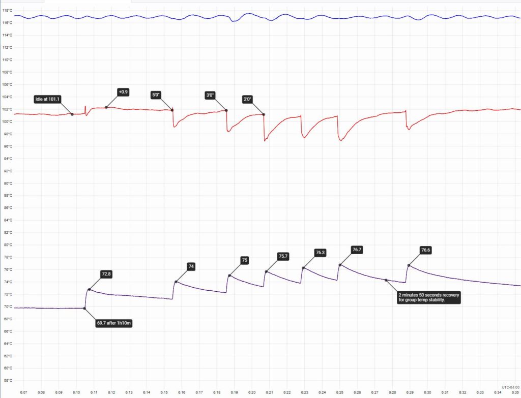
Blue – Boiler
Red – Brew reservoir
Purple – Group neck

Now, although the results aren’t perfect, it shows that the concept works. The group heat gain for successive (unnaturally) rapid shots has been significantly diminished and the recovery time for the group is less than half of what it was (less than 3 minutes). The length of the injector plays an important role in how much boiler temperature HX water mixes with the line water and consequently in the temperature of the water that reaches the brew reservoir. But, as I said, this is a one-shot fabrication and is too much trouble to alter. It would be much easier to change and/or maintain if the injector tube screwed into a straight length of larger diameter tube that maybe ran directly to the group right through the boiler, maybe on a diagonal…

Wait – someone already thought of that.

Enough porridge already.

Posted on Leave a comment

When last we left our heroes…

I have an indelible childhood memory of watching reruns of serialized television from the 50s in black and white. At the end of each episode the heroes always seem to be in an entirely intractable position: hurtling towards certain death as the car / rocket ship plunges to the ground or tied up as the bad guys abandon them to their fate as the building burns / volcano erupts. How do they escape? “Find out next week” on …

During the interlude since the last episode (during which I can assure you that the heroes have been frantically filing away at their shackles) I took stock. Here is the state of the production:

Frame – complete & painted. 100%

Cable harness – all modules of the cable harness are complete. A few remain to install with the bodywork. 100%

Controller – four out of five boards designed, tested and in production. One board under design revision. Machining and labeling of enclosure, assembly and installation remain. 75%

Firmware – functional with a few small problems to resolve before it is “good enough” as firmware is never “finished”. 90%

Hydraulics – the most complicated part of the plumbing including all tubing runs connected to the four lower boiler ports, the HX, solenoid, manifold and drain are complete. Six upper ports remain. Of these six, three require fabrication of tubing runs. 70%

Boiler – complete & installed. 100%

Group – The main casting is complete (no small milestone), machined and honed. All the fixed components are complete and on the shelf. The spring is out for quotes as are the parts for the piston assembly. One part remains to fabricate in house and then, once all the parts are in, the group can be assembled. 70%.

Bodywork – Two pieces remains to fabricate and one may have to be revisited. 70%

Millwork – LRFs are complete and installed. All of the cup rail parts are fabircated and finished and are waiting for installation. Tap handles are machined but need to be assembled and finished. Stock has been prepared for making the lever and portafilter handles. 85%

After final assembly is complete there remains testing and packing… in short, there are still a few episodes of this particular series left. How many? Find out next week on ….

Posted on Leave a comment

In praise of LRF

1

Left Ring Finger? Long Range Forecasting? Low Resolution Fox? Nope, definitely not the last one (look it up (yet another minor moral quandary about whether something sexist can also be amusing; probably not allowed, but I digress)). No, rather, I offer some small observations on Little Rubber Feet!

LRF are perhaps something that you might not have spent a lot of time thinking about, but they are ubiquitous and surprisingly important. They are a crucial component of almost every single contemporary household object: from the chair I’m sitting in, to the computer monitor in front of me and even the keyboard I writing this with. The underside of your mouse (if you still have one)? LRF, albeit very small and not at all rubbery. You might say that LRF, if one were to stretch the definition just slightly, are the industrial design equivalent of building foundations: the point(s) at which objects touch the surface they rest upon, negotiating the transfer of the load, evening out imperfections and keeping delicate surfaces away from harder ones. They come in a myriad of shapes and sizes. There are hard ones that slide, soft ones that grip and everything in between. In addition to being made from every kind of natural and artificial rubber and plastic imaginable, they also are made from wood, glass, felt, cork and occasionally even metal. The most special LRF are the orphans that turn up on the floor or being chewed on by your pet and or child. They only reveal their origins six months later when you finally find the lamp that now both wobbles and scratches the table. These are also the same kind that, origins revealed, you are guaranteed not to be able to find again or to just have finally thrown away. Not me though. I have a special LRF drawer.

The scale of a single group lever machine comes with a few challenges. Both the porta filter and the lever itself require the user to apply relatively large amounts of force to the device. Ideally, it should resist these forces without moving when they are applied. Although single group machines are quite large and heavy compared to most items that might sit on your counter, they are featherweights compared to multi-group machines. These are just in, custom made from a low-durometer self-adhesive backed 3mm silicone rubber. The weight of the machine forces the soft material to conform to minor imperfections in the supporting surface vastly increasing the contact area and friction. Result? It grips like a barnacle to a rock.

One more tiny detail closer to finishing.

.

.

.

.

1 – Image: Brik Pixel Art Designs by BRIK.

Posted on 1 Comment

The rite of spring

IGOR STRAVINSKY – ERICH AUERBACH / GETTY IMAGES

So Stravinsky’s ballet caused a riot… perhaps it was the shocking juxtaposition of pagan and modern Weltanschauungen, maybe the audience just didn’t like the music. What can I say? Springs are contentious. With that warning, I shall begin trying to unravel the (minor) mysteries of one particular spring.

A little more than a year ago, it was brought to my attention that replacement springs for the Brugnetti Aurora lever group were no longer available. I checked a number of suppliers and looked for substitutes without any success and I immediately went to my local parts dealer and bought the rest of their stock – a shockingly large number: four.

This is a problem if you are me and want to make new groups, or, if you are not me, repair old ones. So I took the dive into spring design and started to think a bit more carefully about a part that I had presumed was going to be “off the shelf”.

I have since come to the conclusion, for a number of reasons that will further elucidated, that the spring that was sold to me as a replacement for part number A.29 for the Aurora group, may not be, well, a replacement for part number A.29.

When I changed the spring on my first machine (well before I embarked on this voyage deep into the jungle down the Congo River) I noticed that the new one was a little taller than the original, making it quite a bit more difficult to install. Installed it was however, and I thought no more about it. That particular machine dates from 1987 and was rebuilt by a local dealer in the mid 90s – but may well have kept its original spring given how much of a hassle they are to change.

Under normal operation, springs will deliver an amount of force that is directly proportional to the distance they are compressed: F = kx (where F is Force, x displacement and k is the spring constant). Put another way the spring constant is simply how much force the spring imparts per unit of compression. So determining the spring constant can be done by measuring force versus displacement. This is the setup used – the force gauge (i.e. bathroom scale) isn’t ideal because of the built-in “intelligence” which automatically tares (zeros out) small readings and shuts off the display, but it does measure up to 175Kg. Displacement is measured using a digital height gauge (not shown) that (as so long as the same datums are used and the gauge isn’t re-zeroed) provides more accuracy than required with enough precision (I can never keep those straight).

I believe that I have identified three different springs that were installed in the Aurora group at various stages:

The replacement “after-market” spring from the local dealer which has an uncompressed length of 133mm.
Antique spring #1 – which has an uncompressed length of 128mm.
Antique spring #2 – which has an uncompressed length of 116mm.

Here are the compression versus force profiles of those three plus a fourth new prototype spring.

The two trials of the after-market 133mm spring suffer from some measurement error – i.e. if you extend the lines back towards the X axis, they don’t intersect the origin coordinates; which they should, as zero spring displacement results in zero force. If they were to be normalized (i.e. shifted down until they would intersect the origin if extended) you can see that they correlate closely with the all of the other trials except the Antique 128mm. In fact the spring constants (calculated using the average slope of all the data points in each trial) for all but the 128mm spring are around 60 N/mm whereas the 128mm is significantly lower at 44 N/mm.

However, the fact that the springs are different lengths is not a minor detail. As the geometry of the piston assembly remains the same, the springs are all compressed to the same size when they are in use i.e. they have an installed length of 96.25mm (corresponding to the lever in the up position) and a fully compressed length (when the lever is in the down position) of 75.5mm.

Installing a springs of different lengths will mean they are operating over different force ranges. The corresponding pressures that the piston will deliver can be easily obtained from the equation P=F/A (where P is pressure, F is force and A is the surface area [19.63cm sq for the 50mm diameter piston in the Aurora group]).

Spring length(mm)Spring constant (N/mm)Force @ fully compressed (N)Pressure (bar)Force @ installed length (N)Pressure (bar)
aftermarket13362.80361118.4230811.8
antique #112844.39233011.914097.2
antique #211659.21239812.211696.0
lapera11661.99251112.812246.2

Presuming that you find tables at all interesting, some interesting points can be drawn from the one above (although now we are getting into subjective and therefore contentious territory). The first line shows that the replacement after-market springs from the local dealer are very likely incorrect as their theoretical operating range is 18-12 bar. I think most people would agree that this is too high. The case for these springs being incorrect is strengthened by the fact that a design analysis of that spring configuration, (i.e. the spring constant, wire size, number of turns, end conditions etc) results in a non-compliant design when used in this application (i.e. the installed length and travel) meaning that it is likely to fail to perform as expected or simply to fail over time.

The second point of interest is that the two antique springs, despite their different properties, yield very similar pressures in the installed configuration – approximately 12bar maximum and 6-7bar minimum. Without knowing more about the provenance of these particular parts, it is hard to know whether they have changed over time or whether they are still operating as designed. However, based on the subjective results of the quality of the coffee that the machine produces when it is operated over this pressure range, I believe that this was the design intent. Further testing of other old springs of known provenance would be helpful to confirm this hypothesis.

For the prototype I chose to use the shorter ~116mm format because it is significantly easier to install and opted for a similar 12-6bar range at the installed configuration. The new spring should be a drop-in replacement for the old Aurora groups.

Prototype Lapera spring on the left, 18bar monster on the right. We fervently hope this little one doesn’t dance herself to death.

Pina Bausch – The Rite of Spring

Posted on Leave a comment

Love in the time of cholera

Don’t know about you, but I think the penguin looks worried.

In these strangest of times, I hope that you are all well.

I’m not sure where to begin really. Writing about small goings on in my tiny corner of the vast tableau of human experience seems rather pointless given what the whole of humanity is currently enduring. But in the hope that some may find these musings mildly amusing and possibly a welcome diversion from the cataclysmic car crash of out there, we humbly soldier on.

I took delivery last autumn of the bulk of the sheet metal work from a new Canadian supplier. Since then, the stainless steel covers have been sitting on the shelf waiting for the completion of the frames so that all the parts that need to be painted can go to the shop at the same time. As those of you who follow the posts on that photo site owned by the social media company with the reputation for (among other things) being extremely cavalier about their users’ privacy will know, the frames were finished some time ago. So now it’s time to put the finishing touches on the covers. A long, long time ago, (you know, in 2020BC) I discovered that the straight folds on two front flanges of the cover didn’t have quite enough relief on the interior flanges (gasp) to allow the requisite over-bend during fabrication. The upshot of this is that the front panels are only nearly, not exactly, at 90 degrees to the sides (re-gasp). Always seeking to shave off another minute source of imperfection, adding a tab that connects the front flanges to the sides will resolve this and have the additional benefit of increasing the overall stiffness.

This of course requires a new tool. One strangely reminiscent of an earwig.

As always, you get what you pay for and this thing is neither terribly expensive nor terribly good. But it will do (some of) the job. As the following test shows, it can produce a mechanically sound, if slightly less than perfect, spot weld.

Bunch o’ tabs cut from some scrap stainless.

A tab spot-welded into place.

BUT… without radical modification, the spot welder can’t be positioned to make the second weld on the front flange. So, it’s back to the old fashioned (i.e. long and slow) way – TIG welding by hand – with a simple jig to get things all orthogonal-like.

Welding thin material is really easy to get wrong. We managed to pull these off without blowing any holes (or at least ones that I will show you pictures of).

Rinse, repeat:

Drive to nearest big-box store for, well, boxes so that they can be shipped to the painters :D

… hmmm, wonder how they turn out.

Posted on Leave a comment

Lenovo Weldcenter

The control components and the wiring for the welding turntable are too delicate to leave exposed to the dust, metal chips and occasional flying tool around the shop. They have to go in a box. I could have drawn one up and had it fabricated along with the rest of the sheet metal parts for the bodywork, but (a) fabrication shops hate/love one-offs and charge accordingly and (b) a recently deceased Lenovo PC (born 2006, died 2019, R.I.P.) seemed like it might fit the bill.

At first glance, just a simple box.

Its apparent simplicity belies an extremely clever design that a lot of people thought long and hard about. It is also a masterclass in metal folding: the sophisticated locking(!) clamshell and double-pivot mechanisms are assembled from stamped and folded parts using only four screws. Very swish.

Having extolled the virtues of the Lenovo case I no longer need to feel guilty about cutting it up. Possibly voiding the warranty?

Time to start putting a few new things inside the now empty box. The heart of the controller is the stepper motor driver: a Geckodrive g203V. The literature states that the V stands for Vampire, as in unkillable. I have thus far failed to find the correct mixture of garlic and silver bullets required to prove them wrong. Other than an issue with making them play nicely with some common motion control boards that have a different electronic setup for their step and direction signals, these things are great, if not particularly cheap.

The heat sink from the GPU on the Lenovo motherboard is just the ticket for the stepper motor driver. It has a convenient spring-steel mounting clip that makes it easy to attach it to the opposing face of the motor mount.

A healthy application of thermal grease on all of the mating surfaces ensures the efficient transfer of heat from the driver to the sink.

Next, the new Weldcenter needs a face plate for the interface which will be made from a small scrap of 1/4″ acrylic. As usual, drawing up the cutouts and programming the CNC takes substantially longer than the actual cutting. Back surface first: a bunch of holes plus a relief pocket for the rotary pots that are designed for thinner material…

…and the front with engraved text for all of the various buttons, switches, sockets and dials.

Test fit of all the pre-wired controls including the LCD interface.

The front side, with residual laser-engraved tennis racket – the acrylic stock is a left-over from a sign project.

There were, of course, a couple of small, but in some cases mildly baffling, errors. The text at the bottom interferes with the mounting screws because I neglected to model them in CAD. Rather more inexplicable is the engraving of the “Gas” text which appears to have been outline, as opposed to single-line, engraved. Don’t know why, nor, as this is strictly a one-off will I spend any more time thinking about it. Much.

All the various bits and pieces stuffed into the box. Top left: the main cooling fan that used to be at the front of the PC. (For the ultra-observant, now you see why the fins of the heat sink below it are not oriented vertically the way they would be normally). Below the stepper controller is a solenoid for controlling the purge gas. Below that the microcontroller. The middle column is a DIN rail with a small (5 watt) 24 volt DC power supply and a bunch of terminal blocks for connecting everything together. The last column on the right is the other two power supplies. This is a bit of a kluge. There were only supposed to be two flavors of DC in the design: 5 volts for the microprocessor and 24 volts for the solenoid and motor and no fan. However, the 24 volt supply was very bulky so I swapped it for a much more compact 60 volt switching supply. The black box is a dual voltage (5 & 12) supply for an external hard drive of which I have many. So… four flavors: microprocessor 5 volt, fan 12 volt, solenoid 24 volt and stepper motor 60 volt. So much for simplicity. As always, the box is about 25% too small for all the stuff. There should really be cable tracks between each column and along the top and bottom. There aren’t so the resulting wiring is not exactly as neat as it might be.

The final piece of the puzzle is a foot control made from a couple of robust momentary switches (the kind used for guitar pedals), a nice metal case (ditto) and some three conductor wire (the extra green wire was spliced on).

The switches are wired in parallel with their corresponding button on the front panel of the interface. Pressing either the button or the foot switch triggers the control.

Finished foot controls. The throttle pedal, which is for an electric scooter and cost less than $10 (Canadian, including shipping), is extremely well made.

The Hall effect sensor inside it however, (the white stuff is silicon and isn’t as disgusting as it looks), is not. Either I killed it by miss-wiring it briefly while I was hooking everything up, or it was lousy to begin with (I lean towards the latter). Either way, a broken sensor means no throttle pedal which means the entire machine is about as useful as a third shoe. So I replaced the sensor with a brand-name version over-nighted from MagicKy (aka Digi-Key) – (which cost more than the entire pedal after shipping). Hall effect sensors work by measuring the flux of the magnetic field that passes through them. The stronger the magnetic field – i.e. the closer the magnet is to the sensor, the stronger the signal. The silver lining of replacing the sensor with a high quality part is that it has a bigger range – it detects lower strengths of the magnetic field and outputs lower minimum and higher maximum signal voltages, so the pedal response is far more sensitive. Coupled with a pseudo-logarithmic curve which is applied to the output from the sensor in software, the throttle pedal now allows very precise control at the lower end of the speed range where it is most important.

Et voila, the finished LenovoⒸ Weldcenter – running Windows Vista (ok, no it doesn’t).

The LED display shows the low and high RPM settings that are mapped to the throttle pedal output. The rewind amount is a fraction of a single rotation at high speed – a tap on the rewind button and the turntable reverses by that amount. In retrospect this turns out to possibly not have been the best way to do this as in practice the amount of rewind required changes too often. At some point I may (or possibly may not) add a mode where the rewind is active while the button/pedal switch is depressed. It also occurred to me too late that I could combine the two foot switches in a single cable and XLR jack, which means that I now have a spare jack for the ion cannon accessory.

A quick test with some scrap tubing before all the kinks with the code were worked out.

Posted on Leave a comment

Framework – 2

Ok, so I don’t have to climb a ladder quite that big to put the finishing touches on this frame. That is a lot of parts to design, fabricate and keep track of. Without computers. At once humbling and further proof, should any be required, that Zeppelins are insane.

Cross bars made from cold-rolled 1080 carbon steel. The small ones are for the top bar and the large ones for the bottom. These are rough-cut to length and squared and ground (sanded really) to just under their nominal finished length. These parts do not play a role in locating the sides of the frame (the laser-cut parts do that job), but they do locate the group and the taps so there can’t be too much play. In practice this translates to a length of within 0.2mm of, but always less than, nominal.

Drilled, countersunk, tapped and deburred.

The uprights are cut from lengths of rectangular tubing and are temporarily tagged and machined in pairs. This means that the left and right halves of each pair is the same length and, where necessary, hole placement is symmetrical. The baby 1″ clamps are made by Kant. The design with the central pivot eliminates twisting so the clamping force always remains axial between the jaws. Consequently, parts don’t slip out of alignment as the clamp distorts when they are tightened. Very clever, very useful.

The tops of the tubes will be filled with a coupon of 1/8th steel which is drilled and tapped for the ball studs that hold the cup warmer in place. This is the first time that all of the parts of this iteration of the design are being assembled so the coupons are left blank in order allow adjustment of the hole position, if necessary. Once I know that everything fits as it is supposed to the holes can be laser-cut the next time this part is ordered.

All of these things meet each other for the first time in the upright frame assembly. <digression> Interesting word thing. At some point in my education I learnt that the English word “thing“, along with its German and Dutch cousin “Ding/ding” and Scandinavian “ting“, original meant assembly, as in an assembly of people. A thing was a gathering of the populace to legislate, adjudicate and elect leaders. In other words, it is a precursor to our courts and parliaments rolled into a single time and place. For the Vikings, “Are you going to that thing on Friday night?” meant finding out how many pounds of salt cod your neighbor Leif owed you because his son Svend borrowed your longship without asking and crashed it. </digression>

The pieces are brought together in the jig along with an extra spacer-bar across the top that will not be welded in place. In this particular jig, the left side and bottom rails are installed permanently perpendicular to each other while the rest of the transverse parts are allowed to move slightly from right to left. This permits clamping and means that the frame can be removed from the jig despite the inevitable slight distortion to the thin walled tubing that occurs during the welding.

After beefing up all of the fragile tack welds, the sections of the frame can now finally be united with the words: with this TIG I thee weld. Though admittedly an actual three-way wedding would be a little weird. Front and upright.

Back, front and upright held in place against carefully aligned stops welded to the table.

Almost complete!

Now that the tubes are in their final place the end fillers can be located and fixed with a delicate weld. The gaps are left purposefully so that welds don’t have to be ground where they would interfere with other parts.

A satisfying row of finished frames cooling with a vintage bicycle…

The next step is to cover them in a skin made of cotton painted with aluminum, put a gas bag made from cow intestines inside, fill them with hydrogen and fly them to New York. Perhaps not. (What were they thinking?)

Posted on Leave a comment

Halloween special – framework 1

©iStockphoto.com/GloablIP

Have you noticed that the vast majority of how-to videos about metal work, welding, car repair etc all have heavy metal soundtracks? Not around here. In fact, most of the shops that I go to have a top 40 station on – you know the kind – where it is always time to ‘check on the traffic’. Not that I have anything against heavy metal mind you – it just seems like it sits firmly on the opposite side of the spectrum from what Tom Waits would describe as “easy listening music”. I find that unless the work I’m doing involves deliberately breaking things, heavy metal (unless you have the volume really, really low, and what would be the point of that) is just too deleterious to the concentration.

Meanwhile, the new sheet metal supplier shipped the bulk of the parts for the frame and the bodywork. I started cutting the pallet wrap before I remembered to take a photo. Patience is overrated.

Many good things in this shipment, but the most exciting part (to me, at any rate) is the third generation frame design. Yes, only here can you have a third generation without the first two having being made available for sale :). The new frame base parts are made from 0.120″ HRPO steel (Hot Rolled Pickled and Oiled – do you want fries with that?). Why this material? Well, stainless is three times the price and at least three times more difficult to work and would therefore be prohibitively and needlessly expensive. Galvanneal is theoretically better, but would still have plain old steel exposed at all the cut edges. Most importantly, welding Galvanneal without a full face mask, forced clean-air supply and complete ventilation of off gases leads to an early and unpleasant death. So that is kind of out. I thought about it mind you.

Unlike the previous versions (which in fairness were prototypes) that were cut from flat stock and formed using a somewhat simpler hand-bender, these are CNC laser-cut from sheet stock and CNC folded. The precision is, if you will pardon the pun, mind bending. The width across the two bends, which is a compound error (one bending error added to the next) is getting fairly close to the measurement error of my metrology equipment. Which, if you care about such things, is at least one whole order of magnitude higher than the design specification. This is a nice problem to have.

All of the frame corner brackets plus an extra one for the business end of the electronics box.

Frame spacer. This is an deluxe addition to the new frame design which helps with strength, alignment and precision. Using a laser-cut part means that the fame width, which is critical for a good fit of the bodywork, will have very high repeatability (precision and accuracy for a change!).

So that, apart from a couple of tiny details which we will get to later, is it for the “made-by-others” parts. Now for the in-house bits. The front corner brace doubles as a support for the electronics box. It receives a stainless self-cinching threaded insert – because tapping holes is boring and slow.

Sometimes you could have parts made, but unless you need 1000 pieces the time spent preparing drawings, requesting quotes, tracking packages etc would be more than just making them yourself – even if you don’t have the proper tools. The drip tray retaining detent is a good example. It’s just a piece of stainless wire (aka welding rod) cut to length and bent to 90 degrees. A simple thing, but without it the spring clips that hold the drip tray in place would have to be a friction fit against the frame. Which would wear the paint . Which just wouldn’t be cricket.

Frame preparation. So the right way to do the next bit is to use a robotic capacitive discharge stud welder. But I checked all of the tool drawers in the shop three times and I couldn’t find one. Home Depot didn’t have one either. Guess it has to be done the wrong way for now. All of the little holes in the frames are laser-cut to just under 4mm. This makes them both easy and fast to tap at M4 with a power tool and guide block. Once tapped, the stainless threaded studs can screwed in temporarily and perfectly aligned for welding. Side note: the 12mm M4 threaded studs had to be custom made.

Before welding.

And after.

Then all of the frames get introduced to “Rocky”, the new finishing machine. Rocky is shy, so no picture for the moment, but he does a good job: if you look really closely you can see the dots of different color where the stainless welds have been blended into the mild steel frames.

Two final details to take away for today:

1 – “But why not just use nuts and bolts instead of going to all the trouble of welding (custom made!) stainless studs?” Well, because nuts and bolts would mean in-your-face visible fasteners on the exterior and that, at this particular epicenter of fastidiousness, is just not on.

2 – Even though the frame will be powder-coated, the frame detent and the threaded studs will be exposed as they wear, thus they are made of stainless steel.

Posted on 1 Comment

Very fine

August is very fine. People take holidays. In France and other places in Europe where the sun shines more than occasionally, things start slowing down in July and people “faire le pont” until sometime in late September when they finally remember they had a job. Trying to do anything other than sitting by the pool and taking four hours for lunch (i.e. an hour longer than usual) in August in Italy just isn’t worth attempting. Here in Montreal we are more organized; we like to do things together: along with Moving Day, July 1st, when everyone moves at the same time (Which is insane. Try to find moving truck on that day. I’m not making this up.) we also, as anyone who lives here can attest, tear up all of our roads and rebuild all our overpasses and bridges at the same time. It is more efficient to wait fifty years and then get it all done in one go, ripping-off-the-band-aid-style. Economies of scale you know. We also have this thing called the The Construction Holiday. Towards the end of July, once we are done ripping up the asphalt and putting out the traffic cones, we all go on our government mandated holiday for exactly two weeks. On the same day. We also all come home at the same time. Over the interchanges that we are rebuilding and along the roads we tore up before we all went on holiday. Sensible I call it.

1

Welding the boiler together is a complicated set of procedures. Each type of weld requires a different setup and either a judicious application of inert welding gas, a custom heat-sink or both. Some operations render others either difficult, or in some cases impossible, so it is critical to get the assembly order right. To further complicate matters, each weld introduces some distortion in the parts: more or less depending on their geometry and the amount of heat that goes into the weld.

The HX tubes are easy. The size and fit of the parts makes for a simple weld that is almost invisible.

Ditto (once the heat-sink is made) for the bolt ring.

Just load your nine-shooter and fire away!

All the bolt rings were welded up in about an hour.

Fitting the HX tube in place requires a more complicated setup as both the inside of the boiler and the HX tube have to be purged with inert gas during the weld.

The group mounting flange and brew reservoir meet for the first time.

The end flanges are also done using the turntable (a.k.a. the Ouroboros machine).

A few welds later and after some clean-up: the first full-stainless diagonal heat-exchange boiler off the production line.

This one is now ready for a few tests before the rest are assembled. Mistakes at this point would be, ermm, disappointing.

.

.

.

.

1 – MONTREAL, QUE.: AUGUST 21, 2014 — Construction cones line Rene Levesque Blvd east of Atwater Street in Montreal, on Thursday, August 21, 2014. (Dave Sidaway / THE GAZETTE) Web 4×3 ORG XMIT: POS1410031753473482

Posted on Leave a comment

Ouroboros – part II

At its simplest: A circle is a … closed curve that divides [a] plane into two regions: an interior and an exterior. But it is so much more than that. One of the more marvelous properties of the circle is that, by definition, all radii are perpendicular to the circumference. Though seemly obvious, this has the convenient side-effect of transferring pressure, which acts outwards equally (i.e. along all the radii simultaneously) over the surface area of its containing vessel, into two force vectors that are perpendicular to each radius and tangent to the circle at all points around the circumference. The net result is that the pressure is converted into pure tension: rather than bending, the circular ring just wants to get bigger, elongating the material. Because this happens to be the way in which metal is the strongest, it is also the most efficient way in which to use it, requiring the least amount of material to contain a given pressure. Which is, of course, the reason that pipes and other pressure vessels are round (or, more ideally, spherical, but don’t get me started on spheres).

In the interim, I caused the translocation of a low-quality 1″ bearing from its previous resting place to my doorstep in exchange for a small amount of the most widely-known social construct most often referred to as money. And I made a plan.

The shaft is made from the same cold-rolled steel stock that the lever handles were machined from.

The crown gears have grooved hubs so that they can be keyed to their shafts but I had no key stock on hand. I cut some out of a piece of scrap – which was only somewhat quicker than going all the way to the specialty hardware store – who may or may not have had any (“Did you say ‘metric’ key stock?”).

Milling the slot in the shaft is a lot easier than cutting the groove in the hubs :)

Ah yes. I love it when things fit first time.

The other motivation for using the big cast iron face plate from the lathe is that has the same mounting system as all the other lathe chucks. So rather than mounting the face plate directly to the shaft, I am making a back or adapter plate from some mic6 aluminum (that has been patiently and unknowingly waiting for this day) so that all the other chucks will fit the turn-table.

Test fitting the back plate to the shaft.

Things are coming together.

Now we just need a nice neat control system, which I absolutely promise to clean up and put in a proper box very very soon.

But for now, I can’t wait to give it a test drive.

And so we return to where we started; It always comes back around. Ouroboros: the snake that eats its tail.